IP intercom system October 2013 – Ed.1.
October 2013 – Ed.1.0 E400 family. Control and communications protocols Index Chapter 1. Introduction .................................................................................................................................. 1 1.1 General system description .................................................................................................................. 1 1.2 VoIP technology: a brief description .......................................................................................
October 2013 – Ed.1.0 Chapter 3. Audio communication using RTP and G.711-A ........................................................................... 23 3.1 Encoding ............................................................................................................................................. 23 3.2 Decoding............................................................................................................................................. 25 Chapter 4. SIP ...........................
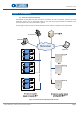
October 2013 – Ed.1.0 Chapter 1. Introduction 1.1 General system description The EQUITEL modules E401 and E451 have been conceived to be used in telephony, intercom and audio distribution systems over an Ethernet/IP network, using VoIP technology standards but adapted to the particular needs of security and surveillance systems. The topology of a possible intercom network based on those modules is depicted in the scheme below: Figure 1.
October 2013 – Ed.1.0 On the left side of the figure it is shown an IP intercom network using E401 OEM boards. Some minimum (1) elements must be added to build, for example, an intercom with it. . On the right side we have depicted an intercom network with E451 units. Regarding the communications, each one of the modules E401 and E451 is an Ethernet device that publishes a different IP address. This way, at a software level, there is no distinction between E401 and the intercom E451.
October 2013 – Ed.1.0 telephone list in the network in constantly updated, as well as its characteristics. The most important characteristic of a telephone that the PBX must know is its IP address, for it has to associate it to a determined identifying name (extension name) In the example in Figure 3 we want to associate the extension 100 to the telephone on the left side, while the telephone on the right is going to be assigned the 200. Both telephones IP addresses have been assigned by a DHCP server.
October 2013 – Ed.1.0 invitation; the ring tone begins to sound and sends a message to the PBX. This message is resent by the PBX to the telephone that originated the call which in turn emits the tone. IP network IP Telephone 192.168.1.25 Ringing... Ringing... IP Telephone 192.168.1.99 Switchboard (PBX) Figure 5. VoIP.
October 2013 – Ed.1.0 Step 5: End of communication When one of the links decide to end the communication, it cuts the audio stream and sends a message to the PBX informing about this. Figure 8. VoIP. End of communication In all this process there are two parts clearly differentiated: the control of the communication establishment or session (steps 1, 2, 3 and 5) and the vocal communications (step 4).
October 2013 – Ed.1.0 Chapter 2. IP intercom systems communications structure EQUITEL IP intercom systems support three independent alternatives or working modes to implement the functionality of IP communication. Parallel to the chosen working mode for the audio communication, a management software implementing EQUITEL proprietary protocol is necessary, to remotely manage the auxiliary inputs and outputs of the modules E401 and E451.
October 2013 – Ed.1.0 2.1 Calls establishment and control: EQUITEL proprietary protocol According to EQUITEL proprietary protocol, the communications between the control center and the E400 modules are based on a “delivery-answer” scheme. That is, any of the links willing to communicate with the other one will send a message, and it is compulsory to receive an answer from the callee.
October 2013 – Ed.1.
October 2013 – Ed.1.
October 2013 – Ed.1.0 2.1.1. Call, answer and audio control The modules E400 accept a button dedicated to user calls. The call generation process using EQUITEL proprietary protocol is shown in Figure 10. Figure 10. Call establishment process When the call button is activated, E400 sends a DEMCALL message to the controller. Should it receive the corresponding ACK, it begins to play the prerecorded message “calling tone”, and waits for the controller to activate audio.
October 2013 – Ed.1.0 2.1.1.1. DEMCALL message This message is sent from a module E400 towards the controller to indicate that the user call button has been pressed. Address: E400 CC Syntax: Command: DEMCALL Parameters: None When an E400 module sends this message, it waits to receive the corresponding ACK. 2.1.1.2. ACK_DEMCALL message This is the answer to a DEMCALL message that the controller must sent back to E400. Address: CC Syntax: Command: ACK_DEMCALL Parameters: None 2.1.1.3.
October 2013 – Ed.1.0 Example: STARTAUDIO 192.168.1.10/66000& Within the message data, the controller indicates to the E400 to which IP address and port the RTP audio packets must be sent. This IP address does not have to be the controller’s. It can be any other element within the network capable of receiving coded RTP audio according the standard G.711-A and decode it.
October 2013 – Ed.1.0 2.1.2. Inputs and outputs control Both E401 and E451 have some auxiliary inputs and outputs. The difference between them is the number and the possibility of configuring their address (input/output) and its initial status. • E401 has up to 18 general purpose inputs/outputs, and any of them can be configured as input or output by means of the suitable command. Please, check the specific documentation for a more detailed description of the accessibility to these inputs/outputs.
October 2013 – Ed.1.0 2.1.2.3. CONFIGPPORT message This command is valid only for E401. This is the message sent by the controller to change the available inputs/outputs configuration. This configuration will be saved.
October 2013 – Ed.1.0 2.1.2.6. ACK_ WRITEPPORT message This is the message that E400 has to send back as the answer to a WRITEPPORT. Address: E400 Syntax: Command: ACK_WRITEPPORT Parameters: None 2.1.2.7. CC READPPORT message This is the message that the controller sends to consult the value of the pins configured as inputs/outputs. Address: CC E400 Syntax: Command: READPPORT Parameters: None E400 sends the message PPORT with each input/output value. 2.1.2.8.
October 2013 – Ed.1.0 2.1.2.9. CHANGEPPORT message This is the message that any of the systems of the family E400 sends when detecting a change in any of their inputs. This message contains the information related to the inputs status change and furthermore it informs about the outputs status. The possibility of using or not this message is enabled by configuring the web server. It will be automatically sent to the controller every time there is a change in any of the inputs.
October 2013 – Ed.1.0 2.1.3. Test and maintenance Within EQUITEL proprietary protocols there are several commands to make tests and help in maintenance tasks. The most important commands are the ones informing about the system status (QRYSYSINFO) and keeping the communications (KEEPALIVE). The first one checks that E400 is working fine and gives information about the system status in that moment. The second one is used to keep the communications with the equipment.
October 2013 – Ed.1.0 2.1.3.3. KEEPALIVE message This is the message that the controller sends to maintain the communication established with E400. Address: CC E400 Syntax: Command: KEEPALIVE Parameters: None Once a connection between the controller and the E400 unit has been established, and the use of this command has been configured, the E400 devices wait to receive messages from the controller at a lower rhythm than the configured expiry time.
October 2013 – Ed.1.0 2.1.3.6. ACK_PLAYTONE message This is the message that E400 sends to the controller when answering to a PLAYTONE one. Address: E400 CC Syntax: Command: ACK_PLAYTONE Parameters: Command status (OK/NOK) E400 shows success or failure in playing the message with OK or NOK, respectively. 2.1.3.7. WORKINGMODE message This is the message that the controller sends to enquiry E400 about its working mode.
October 2013 – Ed.1.0 2.1.4. Communications supervision SIP If we configure the module E400 in any of the working modes using the SIP protocol (SIP with PBX or P2PSIP), we can implement a VoIP network without needing any controller. However, optionally we can add a controller to the network with the task of supervising the calls (to register them), and to control the auxiliary inputs and ouputs. 2.1.4.1.
October 2013 – Ed.1.0 2.1.4.5. INCALLRINGING message This is the message sent from a module E400 to indicate that it has received an incoming call query via the SIP protocol. Address: E400 CC Syntax: Command: INCALLRINGING Parameters: None After sending this message, E400 waits to receive the corresponding ACK_INCALLRINGING. 2.1.4.6. ACK_ INCALLRINGING message This is the message that the central must send back to a module E400 when receiving the message INCALLRINGING.
October 2013 – Ed.1.0 2.1.4.10. ACK_ DISCONNECTEDCALL message This is the message that the control center has to send back to an E400 as the answer to a message DISCONNECTEDCALL.
October 2013 – Ed.1.0 Chapter 3. Audio communication using RTP and G.711-A The audio communication within EQUITEL IP intercom system (E401 AND E451) uses the RTP protocol with the G.711-A encoding. This communication implies two processes: encoding and decoding. With regards to encoding, the equipments E401 and E451 send the RTP stream to the indicated IP address and port in the communication establishment phase.
October 2013 – Ed.1.0 PCM sample (without sign) P10 0 0 0 0 0 0 0 1 P9 0 0 0 0 0 0 1 A P8 0 0 0 0 0 1 A B P7 0 0 0 0 1 A B C P6 0 0 0 1 A B C D P5 0 0 1 A B C D - G.711-A data (without sign) P4 0 1 A B C D - P3 A A B C D - P2 B B C D - P1 C C D - P0 D D - G6 0 0 0 0 1 1 1 1 G5 0 0 1 1 0 0 1 1 G4 0 1 0 1 0 1 0 1 G3 A A A A A A A A G2 B B B B B B B B G1 C C C C C C C C G0 D D D D D D D D To obtain the value of the G.
October 2013 – Ed.1.0 (7) receivers to distinguish the packet content. These field values are normalized by IANA . For the audio encoded in G.711-A the value for this field is 8. Sequence: 16 bits number identifying each packet consecutively. It is used by the receiver to reorder the packets if necessary. TimeStamp: This is a 32-bit time stamp indicating the transmission moment of each packet since the session initiation. The units in which time is measured depend on the type of content. For G.
October 2013 – Ed.1.0 Chapter 4. SIP The SIP protocol is defined under the standard RFC 3261 and encompasses the initiation, management, modification and finalization of multimedia services exchange sessions among several participants, through digital networks, telephone calls, video-conferences, delivery of multimedia contents… The most common application of this protocol nowadays is the management of VoIP calls (in the point 1.2 we have given a brief overview of this technology).
October 2013 – Ed.1.0 In summary, it is the one in charge of establishing the sessions and putting in contact one link with another in communication. In the example of IP telephony, the registrar and SIP servers are within the same element, normally the SIP switchboard or PBX. VoIP Gateway When elements of different technologies are to interface, we have to use Gateways.
October 2013 – Ed.1.0 Once the modules E401 and E451 have been properly configured in the switchboard, register with it and we will be able to make / receive calls directly to / from IP telephones. (9) they have to The advantage of working in this mode against P2P-SIP that we will explain now is given by the PBX itself, since it allows a much better communications management with supervision tasks, calls transfers, etc.
October 2013 – Ed.1.0 P2P-SIP mode 1. Set the IP telephone, not requiring registering with a PBX, assigning it an extension and the (11) . It is important the telephone to have the capacity of required data to make a call understanding the audio codec G711-A, which is the one used by E451. 2. Set the E451, assigning an extension to each one of them. 3. In each one of the E451 units, configure the callee device extension and IP address in a “push-tocall” application.