® Innova Electronics Corp. 11231 Young River Ave. Fountain Valley, CA 92708 Printed in China Instruction MRP #93-0257 Copyright © 2010 IEC. All Rights Reserved.
Table of Contents i YOU CAN DO IT! .............................................................................. 1 SAFETY PRECAUTIONS SAFETY FIRST! ....................................................................... 2 ABOUT THE SCAN TOOL VEHICLES COVERED ............................................................. CONTROLS AND INDICATORS .............................................. DISPLAY FUNCTIONS ............................................................
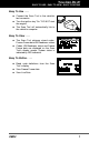
You Can Do It! EASY TO USE - EASY TO VIEW - EASY TO DEFINE Easy To Use . . . . Connect the Scan Tool to the vehicle’s test connector. Turn the ignition key "On.” DO NOT start the engine. The Scan Tool will automatically link to the vehicle’s computer. Easy To View . . . . The Scan Tool retrieves stored codes, Freeze Frame data I/M Readiness status. Codes, I/M Readiness status and Freeze Frame data are displayed on the Scan Tool’s display screen.
Safety Precautions SAFETY FIRST SAFETY FIRST! This manual describes common test procedures used by experienced service technicians. Many test procedures require precautions to avoid accidents that can result in personal injury, and/or damage to your vehicle or test equipment. Always read your vehicle's service manual and follow its safety precautions before and during any test or service procedure.
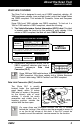
About the Scan Tool VEHICLES COVERED VEHICLES COVERED The Scan Tool is designed to work on all OBD2 compliant vehicles. All 1996 and newer vehicles (cars and light trucks) sold in the United States are OBD2 compliant. This includes all Domestic, Asian and European vehicles. Some 1994 and 1995 vehicles are OBD2 compliant. To find out if a 1994 or 1995 vehicle is OBD2 compliant, check the following: 1. The Vehicle Emissions Control Information (VECI) Label.
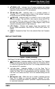
About the Scan Tool CONTROLS AND INDICATORS CONTROLS AND INDICATORS 8 5 7 9 6 1 2 4 3 Figure 1. Controls and Indicators See Figure 1 for the locations of items 1 through 9, below. 4 1. ERASE button - Erases Diagnostic Trouble Codes (DTCs) and "Freeze Frame" data from your vehicle's computer, and resets Monitor status. 2. DTC/FF button - Displays the DTC View screen and/or scrolls the display to view DTCs and Freeze Frame data when more than one DTC is present. 3.
About the Scan Tool DISPLAY FUNCTIONS 5. GREEN LED - Indicates that all engine systems are running normally (all Monitors on the vehicle are active and performing their diagnostic testing, and no DTCs are present). 6. YELLOW LED - Indicates there is a possible problem. A “Pending” DTC is present and/or some of the vehicle's emission monitors have not run their diagnostic testing. 7. RED LED - Indicates there is a problem in one or more of the vehicle's systems.
About the Scan Tool DISPLAY FUNCTIONS 4. DTC Display Area - Displays the Diagnostic Trouble Code (DTC) number and definition. Each fault is assigned a code number that is specific to that fault. 5. MIL icon - Indicates the status of the Malfunction Indicator Lamp (MIL). The MIL icon is visible only when a DTC has commanded the MIL on the vehicle's dashboard to light. 6. Pending icon - Indicates the currently displayed DTC is a "Pending" code. 7.
Onboard Diagnostics COMPUTER ENGINE CONTROLS COMPUTER ENGINE CONTROLS The Introduction of Electronic Engine Controls Electronic Computer Control Systems make it possible for vehicle manufacturers to comply with the tougher emissions and fuel efficiency standards mandated by State and Federal Governments.
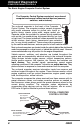
Onboard Diagnostics COMPUTER ENGINE CONTROLS The Basic Engine Computer Control System The Computer Control System consists of an on-board computer and several related control devices (sensors, switches, and actuators). The on-board computer is the heart of the Computer Control System. The computer contains several programs with preset reference values for air/fuel ratio, spark or ignition timing, injector pulse width, engine speed, etc.
Onboard Diagnostics COMPUTER ENGINE CONTROLS Vehicle operating conditions are constantly changing. The computer continuously makes adjustments or corrections (especially to the air/fuel mixture and spark timing) to keep all the engine systems operating within the preset reference values. On-Board Diagnostics - First Generation (OBD1) With the exception of some 1994 and 1995 vehicles, most vehicles from 1982 to 1995 are equipped with some type of first generation On-Board Diagnostics.
Onboard Diagnostics COMPUTER ENGINE CONTROLS Because OBD1 systems only detect failed components, the degraded components were not setting codes. Some emissions problems related to degraded components only occur when the vehicle is being driven under a load. The emission checks being conducted at the time were not performed under simulated driving conditions. As a result, a significant number of vehicles with degraded components were passing Emissions Tests.
Onboard Diagnostics COMPUTER ENGINE CONTROLS Powertrain Control Module (PCM) - The PCM is the OBD2 accepted term for the vehicle’s “on-board computer.” In addition to controlling the engine management and emissions systems, the PCM also participates in controlling the powertrain (transmission) operation. Most PCMs also have the ability to communicate with other computers on the vehicle (ABS, ride control, body, etc.). Monitor - Monitors are “diagnostic routines” programmed into the PCM.
Onboard Diagnostics DIAGNOSTIC TROUBLE CODES (DTCs) OBD2 Drive Cycle - An OBD2 Drive Cycle is an extended set of driving procedures that takes into consideration the various types of driving conditions encountered in real life. These conditions may include starting the vehicle when it is cold, driving the vehicle at a steady speed (cruising), accelerating, etc.
Onboard Diagnostics DIAGNOSTIC TROUBLE CODES (DTCs) Generic DTCs are codes that are used by all vehicle manufacturers. The standards for generic DTCs, as well as their definitions, are set by the Society of Automotive Engineers (SAE). Manufacturer-Specific DTCs are codes that are controlled by the vehicle manufacturers. The Federal Government does not require vehicle manufacturers to go beyond the standardized generic DTCs in order to comply with the new OBD2 emissions standards.
Onboard Diagnostics DIAGNOSTIC TROUBLE CODES (DTCs) DTCs and MIL Status When the vehicle’s on-board computer detects a failure in an emissions-related component or system, the computer’s internal diagnostic program assigns a diagnostic trouble code (DTC) that points to the system (and subsystem) where the fault was found. The diagnostic program saves the code in the computer’s memory.
Onboard Diagnostics OBD2 MONITORS If the conditions that caused the MIL to light are no longer present for the next three trips in a row, the computer automatically turns the MIL “Off” if no other emissions-related faults are present. However, the DTCs remain in the computer’s memory as a history code for 40 warm-up cycles (80 warm-up cycles for fuel and misfire faults). The DTCs are automatically erased if the fault that caused them to be set is not detected again during that period.
Onboard Diagnostics OBD2 MONITORS Non-Continuous Monitors The other twelve Monitors are “non-continuous” Monitors. “Noncontinuous” Monitors perform and complete their testing once per trip. The “non-continuous” Monitors are: Oxygen Sensor Monitor Oxygen Sensor Heater Monitor Catalyst Monitor Heated Catalyst Monitor EGR System Monitor EVAP System Monitor Secondary Air System Monitor The following Monitors will be standard beginning in 2010.
Onboard Diagnostics OBD2 MONITORS Fuel System Monitor - This Monitor uses a Fuel System Correction program, called Fuel Trim, inside the on-board computer. Fuel Trim is a set of positive and negative values that represent adding or subtracting fuel from the engine. This program is used to correct for a lean (too much air/not enough fuel) or rich (too much fuel/not enough air) air-fuel mixture. The program is designed to add or subtract fuel, as needed, up to a certain percent.
Onboard Diagnostics OBD2 MONITORS of) the converter. If the catalytic converter loses its ability to store oxygen, the downstream sensor signal voltage becomes almost the same as the upstream sensor signal. In this case, the monitor fails the test. The Catalyst Monitor is supported by “spark ignition” vehicles only. The Catalyst Monitor is a “Two-Trip” Monitor. If a fault is found on the first trip, the computer temporarily saves the fault in its memory as a Pending Code.
Onboard Diagnostics OBD2 MONITORS solenoid (depending on solenoid design). The purge solenoid opens a valve to allow engine vacuum to draw the fuel vapors from the canister into the engine where the vapors are burned. The EVAP Monitor checks for proper fuel vapor flow to the engine, and pressurizes the system to test for leaks. The computer runs this Monitor once per trip. The EVAP Monitor is supported by “spark ignition” vehicles only. The EVAP Monitor is a “Two-Trip” Monitor.
Onboard Diagnostics OBD2 MONITORS functions when the computer is in closed-loop. A properly operating oxygen sensor reacts quickly to any change in oxygen content in the exhaust stream. A faulty oxygen sensor reacts slowly, or its voltage signal is weak or missing. The Oxygen Sensor Monitor is supported by “spark ignition” vehicles only. The Oxygen Sensor Monitor is a “Two-Trip” monitor. If a fault is found on the first trip, the computer temporarily saves the fault in its memory as a Pending Code.
Onboard Diagnostics OBD2 MONITORS NOx Aftertreatment Monitor - NOx aftertreatment is based on a catalytic converter support that has been coated with a special washcoat containing zeolites. NOx Aftertreatment is designed to reduce oxides of nitrogen emitted in the exhaust stream. The zeolite acts as a molecular "sponge" to trap the NO and NO2 molecules in the exhaust stream. In some implementations, injection of a reactant before the aftertreatment purges it.
Onboard Diagnostics OBD2 MONITORS PM Filter Monitor - The particulate matter (PM) filter removes particulate matter from the exhaust stream by filtration. The filter has a honeycomb structure similar to a catalyst substrate, but with the channels blocked at alternate ends. This forces the exhaust gas to flow through the walls between the channels, filtering the particulate matter out.
Onboard Diagnostics OBD2 MONITORS Name of Monitor A B C D E F Comprehensive Component Monitor Continuous 1 2 1 3 40 Misfire Monitor (Type 1 and 3) Continuous 1 2 1 3 - similar conditions 80 Misfire Monitor (Type 2) Continuous 1 3 - similar conditions 80 80 Fuel System Monitor Continuous 1 1 or 2 1 3 - similar conditions Catalytic Converter Monitor Once per trip 1 2 1 3 trips 40 Oxygen Sensor Monitor Once per trip 1 2 1 3 trips 40 Oxygen Sensor Heater Monitor On
Preparation for Testing BEFORE YOU BEGIN - VEHICLE SERVICE MANUALS BEFORE YOU BEGIN Fix any known mechanical problems before performing any test. See your vehicle's service manual or a mechanic for more information. Check the following areas before starting any test: Check the engine oil, power steering fluid, transmission fluid (if applicable), engine coolant and other fluids for proper levels. Top off low fluid levels if needed. Make sure the air filter is clean and in good condition.
Using the Scan Tool CODE RETRIEVAL PROCEDURE CODE RETRIEVAL PROCEDURE Never replace a part based only on the DTC definition. Each DTC has a set of testing procedures, instructions and flow charts that must be followed to confirm the location of the problem. This information is found in the vehicle's service manual. Always refer to the vehicle's service manual for detailed testing instructions. Check your vehicle thoroughly before performing any test. See Preparation for Testing on page 24 for details.
Using the Scan Tool CODE RETRIEVAL PROCEDURE 6. The Scan Tool will automatically start a check of the vehicle’s computer to determine which type of communication protocol it is using. When the Scan Tool identifies the computer’s communication protocol, a communication link is established. The protocol type used by the vehicle’s computer is shown on the display. A PROTOCOL is a set of rules and procedures for regulating data transmission between computers, and between testing equipment and computers.
Using the Scan Tool CODE RETRIEVAL PROCEDURE 8. To read the display: Refer to DISPLAY FUNCTIONS on page 5 for a description of display elements. A visible icon indicates that the Scan Tool is being powered through the vehicle’s DLC connector. A visible icon indicates that the Scan Tool is linked to (communicating with) the vehicle’s computer.
Using the Scan Tool CODE RETRIEVAL PROCEDURE Yellow LED - Indicates one of the following conditions: PENDING CODE PRESENT - If the yellow LED is lit, it may indicate the existence of a pending code. Check the Scan Tool’s LCD display for confirmation. A pending code is confirmed by the presence of a numeric code and the word PENDING on the Scan Tool’s LCD display.
Using the Scan Tool CODE RETRIEVAL PROCEDURE - If the correct manufacturer is shown, press the LD/ENTER button to continue. - If the correct manufacturer is not shown, press the DTC/FF button to return to the list of vehicle manufacturers. If the manufacturer for your vehicle is not listed, use the DOWN button, as necessary, to select Other manufacturer and press the LD/ENTER button for additional DTC information.
Using the Scan Tool ERASING DIAGNOSTIC TROUBLE CODES (DTCs) 12. Determine engine system(s) condition by viewing the Scan Tool’s display for any retrieved Diagnostic Trouble Codes, code definitions, Freeze Frame data and Live Data, interpreting the green, yellow and red LEDs. If DTC’s were retrieved and you are going to perform the repairs yourself, proceed by consulting the Vehicle’s Service Repair Manual for testing instructions, testing procedures, and flow charts related to retrieved code(s).
Using the Scan Tool ERASING DIAGNOSTIC TROUBLE CODES (DTCs) The ERASE button is active only when the Scan Tool is in DTC display mode. The ERASE button is not active when viewing Freeze Frame data, or when the Scan Tool is in “Live Data” mode. If you change your mind and do not wish to erase the codes, press the LD/ENTER button to return to the code retrieval function. If you wish to continue, press the ERASE button again to erase DTCs from the vehicle’s computer. 4.
Live Data Mode VIEWING LIVE DATA The Scan Tool is a special tool that communicates with the vehicle's computer. The Scan Tool lets you view and/or "capture" (record) "realtime" Live Data. This information includes values (volts, rpm, temperature, speed etc.) and system status information (open loop, closed loop, fuel system status, etc.) generated by the various vehicle sensors, switches and actuators.
Live Data Mode CUSTOMIZING LIVE DATA If communication with the vehicle is lost while viewing Live Data, a “Communication Lost" message shows on the Scan Tool's display. 5. If you experience vehicle problems, view and/or compare the Live Data (PID) information displayed on the Scan Tool to specifications in the vehicle's repair manual. If desired, you can "customize" the Live Data display to show only those PIDs you are interested in viewing. See Customizing Live Data (PIDs) below for details. 6.
Live Data Mode CUSTOMIZING LIVE DATA To deselect a currently selected PID, highlight the PID, then press the LD/ENTER button. The checkmark will be removed from the checkbox. 4. When you are finished making your selection(s), scroll to the end of the PID list and highlight the word DONE, then press the LD/ENTER button. The Scan Tool is now in "Custom Live Data" mode. Only the PIDs you selected are shown on the Scan Tool’s display.
Additional Functions VIEWING VEHICLE INFORMATION VIEWING VEHICLE INFORMATION The Scan Tool offers three options for retrieving reference information for the vehicle under test; Vehicle ID, Available Modules and IPT (Inuse Performance Tracking). Retrieving Vehicle ID Information The Vehicle ID function is applicable to model year 2000 and newer OBD2-compliant vehicles.
Additional Functions VIEWING VEHICLE INFORMATION Viewing Available Modules The Scan Tool can retrieve a list of modules supported by the vehicle under test. 1. With the Scan Tool in “Live Data” mode (see VIEWING LIVE DATA button on page 32 for details), press and hold the LD/ENTER until the “Mode Selection Menu” appears. button to highlight 2. Use the DOWN Vehicle Information, then press the button. LD/ENTER The Vehicle Information menu displays. button to highlight 3.
Additional Functions O2 SENSOR TEST Use the DOWN button to highlight IPT, then press the LD/ENTER button. A “One moment please . . .” message displays while the requested information is retrieved from the vehicle’s computer. If In-use Performance Tracking is not supported by the vehicle under test, an advisory message shows on the Scan Tool’s display. Press the LD/ENTER button to exit. 3.
Additional Functions ADJUSTMENTS AND SETTINGS For example, O2S12 or O2SB1S2 is the designation for the downstream O2 sensor for cylinder bank 1. The Scan Tool does not perform O2 sensor tests, but retrieves results from the most recently performed O2 sensor tests from the on-board computer's memory. You may retrieve O2 sensor test results for only one test of one sensor at any given time. 1.
Additional Functions ADJUSTMENTS AND SETTINGS Adjust Brightness: Adjusts the brightness of the display screen. Audible Tone: Turns the Diagnostic Tool’s audible tone “on” and “off.” When turned “on,” a tone sounds each time a button is pressed. Unit of Measurement: Sets the Unit of Measurement for the Scan Tool’s display to USA or metric. Accessing the Adjustments and Settings Menu 1.
Additional Functions ADJUSTMENTS AND SETTINGS 2. Press the DOWN button to increase the brightness of the display (make the display lighter). When the maximum brightness setting is reached and the DOWN button is pressed, the display returns to the minimum brightness setting. 3. When the desired brightness is obtained, press the LD/ENTER button to save your changes and return to the Setup Menu. Enabling the Audible Tone button to highlight 1.
Generic (Global) OBD2 PID List The following is a list of Generic (Global) PIDs and their descriptions. Tool Display ACC Pedal D ACC Pedal E ACC Pedal F Air Status Ambient Aux Input Status BARO Unit % % % *C / *F - Value XXX.X XXX.X XXX.X UPS, DNS, OFF XXX PID Description Accelerator Pedal Position D Accelerator Pedal Position E Accelerator Pedal Position F Commanded Secondary Air Status Ambient Air Temperature On / Off Auxiliary Input Status kPa /inHg % *C / *F *C / *F *C / *F *C / *F % XXX / XX.
Generic (Global) OBD2 PID List Tool Display EQ Ratio 14 Unit - Value X.XXX EQ Ratio 21 - X.XXX EQ Ratio 22 - X.XXX EQ Ratio 23 - X.XXX EQ Ratio 24 - X.XXX EVAP Press Pa /in H2O kPa /PSI % kPa /PSI kPa /PSI *C / *F % % % % % g/s ;l b/min kPa /PSI hrs, min - XXXX.XX /XX.
Generic (Global) OBD2 PID List Tool Display O2S B1 S1 mA O2S B1 S1 V O2S B1 S2 O2S B1 S2 mA O2S B1 S2 V O2S B1 S3 O2S B1 S3 mA O2S B1 S3 V O2S B1 S4 O2S B1 S4 mA O2S B1 S4 V O2S B2 S1 O2S B2 S1 mA O2S B2 S1 V O2S B2 S2 O2S B2 S2 mA O2S B2 S2 V O2S B2 S3 O2S B2 S3 mA O2S B2 S3 V O2S B2 S4 O2S B2 S4 mA O2S B2 S4 V O2S Location O2S Location O2S Location O2S Location O2S Location O2S Location O2S Location O2S Location O2S Location O2S Location O2S Location O2S Location O2S Location O2S Location O2S Location OB
Generic (Global) OBD2 PID List Tool Display O2S Location OBD Support OBD Support OBD Support Unit - OBD Support OBD Support OBD Support OBD Support - OBD Support - OBD Support - OBD Support OBD Support - OBD Support - OBD Support - Value O2S42 OBD2 OBD OBD and OBD2 OBD1 No OBD EOBD EOBD and OBD2 EOBD and OBD EOBD, OBD and OBD2 JOBD JOBD and OBD2 JOBD and EOBD JOBD, EOBD and OBD2 On / Off XXX.
Generic (Global) OBD2 PID List Tool Display Veh Speed Warm-up DTC Clr OBD2 Unit km/h / mph - Value XXX / XXX XXX PID Description Vehicle Speed Sensor # Warm-ups since DTC Cleared 45
Notes 46 OBD2
Notes OBD2 47
Notes 48 OBD2
Warranty and Servicing LIMITED ONE YEAR WARRANTY The Manufacturer warrants to the original purchaser that this unit is free of defects in materials and workmanship under normal use and maintenance for a period of one (1) year from the date of original purchase. If the unit fails within the one (1) year period, it will be repaired or replaced, at the Manufacturer’s option, at no charge, when returned prepaid to the Service Center with Proof of Purchase. The sales receipt may be used for this purpose.
® Innova Electronics Corp. 11231 Young River Ave. Fountain Valley, CA 92708 Printed in China Instruction MRP #93-0257 Copyright © 2010 IEC. All Rights Reserved.