® Innova Electronics Corp. 17291 Mt. Herrmann Street Fountain Valley, CA 92708 Printed in Taiwan Instruction MRP #93-0093 Rev. D Copyright © 2009 IEC. All Rights Reserved.
Table of Contents i INTRODUCTION WHAT IS OBD? ........................................................................ 1 YOU CAN DO IT! .............................................................................. 2 SAFETY PRECAUTIONS SAFETY FIRST! ........................................................................ 3 ABOUT THE DIAGNOSTIC TOOL VEHICLES COVERED ............................................................. BATTERY REPLACEMENT .....................................................
Introduction WHAT IS OBD? WHAT IS OBD? The Enhanced CanOBD2 Diagnostic Tool is designed to work on all OBD2 compliant vehicles. All 1996 and newer vehicles (cars, light trucks and SUVs) sold in the United States are OBD2 compliant. One of the most exciting improvements in the automobile industry was the addition of onboard diagnostics (OBD) on vehicles, or in more basic terms, the computer that activates the vehicle’s “CHECK ENGINE” light.
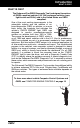
You Can Do It! EASY TO USE - EASY TO VIEW - EASY TO DEFINE Easy To Use . . . . Connect the Diagnostic Tool to the vehicle’s test connector. Turn the ignition key "On.” Press the LINK button. Easy To View . . . . The Diagnostic Tool retrieves stored codes, Freeze Frame data and I/M Readiness status. Codes, I/M Readiness status and Freeze Frame data are displayed on the Diagnostic Tool’s LCD display screen. System status is indicated by LED indicators. Easy To Define . . . .
Safety Precautions SAFETY FIRST! SAFETY FIRST! To avoid personal injury, instrument damage and/or damage to your vehicle; do not use the OBD2 Code Reader before reading this manual. This manual describes common test procedures used by experienced service technicians. Many test procedures require precautions to avoid accidents that can result in personal injury, and/or damage to your vehicle or test equipment.
Safety Precautions SAFETY FIRST! To prevent damage to the on-board computer when taking vehicle electrical measurements, always use a digital multimeter with at least 10 megOhms of impedance. Fuel and battery vapors are highly flammable. To prevent an explosion, keep all sparks, heated items and open flames away from the battery and fuel / fuel vapors. DO NOT SMOKE NEAR THE VEHICLE DURING TESTING. Don't wear loose clothing or jewelry when working on an engine.
About the Diagnostic Tool VEHICLES COVERED VEHICLES COVERED The Enhanced CanOBD2 Diagnostic Tool is designed to work on all OBD2 compliant vehicles. All 1996 and newer vehicles (cars and light trucks) sold in the United States are OBD2 compliant. Federal law requires that all 1996 and newer cars and light trucks sold in the United States must be OBD2 compliant; this includes all Domestic, Asian and European vehicles. Some 1994 and 1995 vehicles are OBD2 compliant.
About the Diagnostic Tool BATTERY REPLACEMENT / ADJUSTMENTS/SETTINGS AND DTC LIBRARY On some Asian and European vehicles the DLC is located behind the “ashtray” (the ashtray must be removed to access it) or on the far left corner of the dash. If the DLC cannot be located, consult the vehicle’s service manual for the location. BATTERY REPLACEMENT Replace batteries when the battery symbol is visible on display and/or the 3 LEDS are all lit and no other data is visible on screen. 1.
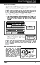
About the Diagnostic Tool ADJUSTMENTS / SETTINGS AND DTC LIBRARY Select Language: Sets the display language for the Diagnostic Tool to English, French or Spanish. Unit of Measurement: Sets the Unit of Measurement for the Diagnostic Tool’s display to USA or metric. Adjustments and settings can be made only when the Diagnostic Tool is NOT connected to a vehicle. To enter the MENU Mode: 1. With the Diagnostic Tool OFF, press and hold the UP button, then press and release the POWER/LINK button.
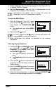
About the Diagnostic Tool ADJUSTMENTS / SETTINGS AND DTC LIBRARY Searching for a DTC Definition Using the DTC Library and DOWN buttons, 1. Use the UP as necessary, to highlight DTC Library in the MENU, then press the ENTER/FF button. The Enter DTC screen displays. The screen shows the code “P0001”, with the “P” flashing. 2. Use the UP and DOWN buttons, as necessary, to scroll to the desired DTC type (P=Powertrain, U=Network, B=Body, C=Chassis), then press the button.
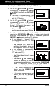
About the Diagnostic Tool ADJUSTMENTS / SETTINGS AND DTC LIBRARY If a definition for the DTC you entered is not available, an advisory message shows on the Enhanced CanOBD2 Diagnostic Tool’s display. 4. If you wish to view definitions for additional DTCs, press the ENTER/FF button to return to the DTC Library screen, and repeat steps 2 and 3. 5. When all desired DTCs have been viewed, press the ERASE button to exit the DTC Library. Selecting the Display Language and DOWN buttons, 1.
About the Diagnostic Tool ADJUSTMENTS / SETTINGS AND DTC LIBRARY Exiting the MENU Mode and DOWN buttons, as necessary, to highlight 1. Use the UP Menu Exit in the MENU, then press the ENTER/FF button. 10 The LCD display returns to the DTC screen (if data is currently stored in the Diagnostic Tool’s memory) or the “To Link” screen (if no data is stored).
Diagnostic Tool Controls CONTROLS AND INDICATORS CONTROLS AND INDICATORS 11 10 7 6 8 9 1 3 2 4 5 Figure 1. Controls and Indicators See Figure 1 for the locations of items 1 through 11, below. 1. ERASE button - Erases Diagnostic Trouble Codes (DTCs), and “Freeze Frame” data from your vehicle’s computer, and resets Monitor status. 2. DTC SCROLL button - Displays the DTC View screen and/or scrolls the LCD display to view DTCs when more than one DTC is present. 3.
Diagnostic Tool Controls CONTROLS AND INDICATORS 5. DOWN button - When in MENU mode, scrolls DOWN through the menu and submenu selection options. When retrieving and viewing DTCs, scrolls down through the current display screen to display any additional data. 6. UP button - When in MENU mode, scrolls UP through the menu and submenu selection options. When retrieving and viewing DTCs, scrolls ups through the current display screen to display any additional data. 7.
Diagnostic Tool Controls DISPLAY FUNCTIONS DISPLAY FUNCTIONS 2 1 11 12 13 3 4 5 6 14 7 10 8 9 Figure 2. Display Functions See Figure 2 for the locations of items 1 through 16, below. 1. I/M MONITOR STATUS field - Identifies the I/M Monitor status area. 2. Monitor icons - Indicate which Monitors are supported by the vehicle under test, and whether or not the associated Monitor has run its diagnostic testing (Monitor status).
Diagnostic Tool Controls DISPLAY FUNCTIONS 7. DTC Display Area - Displays the Diagnostic Trouble Code (DTC) number. Each fault is assigned a code number that is specific to that fault. 8. Test Data Display Area - Displays DTC definitions, Freeze Frame data, and other pertinent test information messages. 9. FREEZE FRAME icon - Indicates that there is Freeze Frame data from “Priority Code” (Code #1) stored in the vehicle’s computer memory. 10.
Onboard Diagnostics COMPUTER ENGINE CONTROLS COMPUTER ENGINE CONTROLS The Introduction of Electronic Engine Controls Electronic Computer Control Systems make it possible for vehicle manufacturers to comply with the tougher emissions and fuel efficiency standards mandated by State and Federal Governments.
Onboard Diagnostics COMPUTER ENGINE CONTROLS The Basic Engine Computer Control System The Computer Control System consists of an on-board computer and several related control devices (sensors, switches, and actuators). The on-board computer is the heart of the Computer Control System. The computer contains several programs with preset reference values for air/fuel ratio, spark or ignition timing, injector pulse width, engine speed, etc.
Onboard Diagnostics COMPUTER ENGINE CONTROLS Vehicle operating conditions are constantly changing. The computer continuously makes adjustments or corrections (especially to the air/fuel mixture and spark timing) to keep all the engine systems operating within the preset reference values. On-Board Diagnostics - First Generation (OBD1) With the exception of some 1994 and 1995 vehicles, most vehicles from 1982 to 1995 are equipped with some type of first generation On-Board Diagnostics.
Onboard Diagnostics COMPUTER ENGINE CONTROLS Because OBD1 systems only detect failed components, the degraded components were not setting codes. Some emissions problems related to degraded components only occur when the vehicle is being driven under a load. The emission checks being conducted at the time were not performed under simulated driving conditions. As a result, a significant number of vehicles with degraded components were passing Emissions Tests.
Onboard Diagnostics COMPUTER ENGINE CONTROLS Powertrain Control Module (PCM) - The PCM is the OBD2 accepted term for the vehicle’s “on-board computer.” In addition to controlling the engine management and emissions systems, the PCM also participates in controlling the powertrain (transmission) operation. Most PCMs also have the ability to communicate with other computers on the vehicle (ABS, ride control, body, etc.). Monitor - Monitors are “diagnostic routines” programmed into the PCM.
Onboard Diagnostics DIAGNOSTIC TROUBLE CODES (DTCs) OBD2 Drive Cycle - An OBD2 Drive Cycle is an extended set of driving procedures that takes into consideration the various types of driving conditions encountered in real life. These conditions may include starting the vehicle when it is cold, driving the vehicle at a steady speed (cruising), accelerating, etc.
Onboard Diagnostics DIAGNOSTIC TROUBLE CODES (DTCs) Generic DTCs are codes that are used by all vehicle manufacturers. The standards for generic DTCs, as well as their definitions, are set by the Society of Automotive Engineers (SAE). Manufacturer-Specific DTCs are codes that are controlled by the vehicle manufacturers. The Federal Government does not require vehicle manufacturers to go beyond the standardized generic DTCs in order to comply with the new OBD2 emissions standards.
Onboard Diagnostics DIAGNOSTIC TROUBLE CODES (DTCs) DTCs and MIL Status When the vehicle’s on-board computer detects a failure in an emissions-related component or system, the computer’s internal diagnostic program assigns a diagnostic trouble code (DTC) that points to the system (and subsystem) where the fault was found. The diagnostic program saves the code in the computer’s memory.
Onboard Diagnostics OBD2 MONITORS If the conditions that caused the MIL to light are no longer present for the next three trips in a row, the computer automatically turns the MIL “Off” if no other emissions-related faults are present. However, the DTCs remain in the computer’s memory as a history code for 40 warm-up cycles (80 warm-up cycles for fuel and misfire faults). The DTCs are automatically erased if the fault that caused them to be set is not detected again during that period.
Onboard Diagnostics OBD2 MONITORS Non-Continuous Monitors The other twelve Monitors are “non-continuous” Monitors. “Noncontinuous” Monitors perform and complete their testing once per trip. The “non-continuous” Monitors are: Oxygen Sensor Monitor Oxygen Sensor Heater Monitor Catalyst Monitor Heated Catalyst Monitor EGR System Monitor EVAP System Monitor Secondary Air System Monitor The following Monitors will be standard beginning in 2010.
Onboard Diagnostics OBD2 MONITORS Fuel System Monitor - This Monitor uses a Fuel System Correction program, called Fuel Trim, inside the on-board computer. Fuel Trim is a set of positive and negative values that represent adding or subtracting fuel from the engine. This program is used to correct for a lean (too much air/not enough fuel) or rich (too much fuel/not enough air) air-fuel mixture. The program is designed to add or subtract fuel, as needed, up to a certain percent.
Onboard Diagnostics OBD2 MONITORS the downstream sensor signal voltage becomes almost the same as the upstream sensor signal. In this case, the monitor fails the test. The Catalyst Monitor is supported by “spark ignition” vehicles only. The Catalyst Monitor is a “Two-Trip” Monitor. If a fault is found on the first trip, the computer temporarily saves the fault in its memory as a Pending Code. The computer does not command the MIL on at this time.
Onboard Diagnostics OBD2 MONITORS into the engine where the vapors are burned. The EVAP Monitor checks for proper fuel vapor flow to the engine, and pressurizes the system to test for leaks. The computer runs this Monitor once per trip. The EVAP Monitor is supported by “spark ignition” vehicles only. The EVAP Monitor is a “Two-Trip” Monitor. If a fault is found on the first trip, the computer temporarily saves the fault in its memory as a Pending Code. The computer does not command the MIL on at this time.
Onboard Diagnostics OBD2 MONITORS exhaust stream. A faulty oxygen sensor reacts slowly, or its voltage signal is weak or missing. The Oxygen Sensor Monitor is supported by “spark ignition” vehicles only. The Oxygen Sensor Monitor is a “Two-Trip” monitor. If a fault is found on the first trip, the computer temporarily saves the fault in its memory as a Pending Code. The computer does not command the MIL on at this time.
Onboard Diagnostics OBD2 MONITORS NOx Aftertreatment Monitor - NOx aftertreatment is based on a catalytic converter support that has been coated with a special washcoat containing zeolites. NOx Aftertreatment is designed to reduce oxides of nitrogen emitted in the exhaust stream. The zeolite acts as a molecular "sponge" to trap the NO and NO2 molecules in the exhaust stream. In some implementations, injection of a reactant before the aftertreatment purges it.
Onboard Diagnostics OBD2 MONITORS PM Filter Monitor - The particulate matter (PM) filter removes particulate matter from the exhaust stream by filtration. The filter has a honeycomb structure similar to a catalyst substrate, but with the channels blocked at alternate ends. This forces the exhaust gas to flow through the walls between the channels, filtering the particulate matter out.
Onboard Diagnostics OBD2 MONITORS Name of Monitor A B C D E F Comprehensive Component Monitor Continuous 1 2 1 3 40 Misfire Monitor (Type 1 and 3) Continuous 1 2 1 3 - similar conditions 80 Misfire Monitor (Type 2) Continuous 1 3 - similar conditions 80 80 Fuel System Monitor Continuous 1 1 or 2 1 3 - similar conditions Catalytic Converter Monitor Once per trip 1 2 1 3 trips 40 Oxygen Sensor Monitor Once per trip 1 2 1 3 trips 40 Oxygen Sensor Heater Monitor On
Preparation for Testing PRELIMINARY VEHICLE DIAGNOSTIC WORKSHEET PRELIMINARY VEHICLE DIAGNOSTIC WORKSHEET The purpose of this form is to help you gather preliminary information on your vehicle before you retrieve codes. By having a complete account of your vehicle's current problem(s), you will be able to systematically pinpoint the problem(s) by comparing your answers to the fault codes you retrieve.
Preparation for Testing PRELIMINARY VEHICLE DIAGNOSTIC WORKSHEET WHEN DID YOU FIRST NOTICE THE PROBLEM: ❏ Just Started ❏ Started Last Week ❏ Started Last Month ❏ Other: m LIST ANY REPAIRS DONE IN THE PAST SIX MONTHS: PROBLEMS STARTING ❏ No symptoms ❏ Cranks, but will not start ❏ ❏ Starts, but takes a long time ❏ Right after vehicle comes to a stop ❏ While idling ❏ During acceleration When parking Will not crank ENGINE QUITS OR STALLS ❏ No symptoms ❏ Right after starting ❏ When s
Preparation for Testing PRELIMINARY VEHICLE DIAGNOSTIC WORKSHEET AUTOMATIC TRANSMISSION PROBLEMS (if applicable) ❏ ❏ ❏ ❏ No symptoms Shifts too early or too late Changes gear incorrectly PROBLEM OCCURS Morning ❏ ❏ ❏ Vehicle does not move when in gear Jerks or bucks Afternoon ❏ Anytime ❏ Hot ENGINE TEMPERATURE WHEN PROBLEM OCCURS ❏ Cold ❏ Warm DRIVING CONDITIONS WHEN PROBLEM OCCURS ❏ ❏ ❏ ❏ ❏ ❏ ❏ ❏ Short - less than 2 miles 2 - 10 miles Long - more than 10 miles Stop and go While turning Wh
Preparation for Testing BEFORE YOU BEGIN BEFORE YOU BEGIN The Enhanced CanOBD2 Diagnostic Tool aids in monitoring electronic- and emissions-related faults in your vehicle and retrieving fault codes related to malfunctions in these systems. Mechanical problems such as low oil level or damaged hoses, wiring or electrical connectors can cause poor engine performance and may also cause a fault code to set. Fix any known mechanical problems before performing any test.
Preparation for Testing VEHICLE SERVICE MANUALS VEHICLE SERVICE MANUALS Always refer to the manufacturer’s service manual for your vehicle before performing any test or repair procedures. Contact your local car dealership, auto parts store or bookstore for availability of these manuals.
Using the Diagnostic Tool CODE RETRIEVAL PROCEDURE CODE RETRIEVAL PROCEDURE Retrieving and using Diagnostic Trouble Codes (DTCs) for troubleshooting vehicle operation is only one part of an overall diagnostic strategy. Never replace a part based only on the DTC definition. Each DTC has a set of testing procedures, instructions and flow charts that must be followed to confirm the location of the problem. This information is found in the vehicle's service manual.
Using the Diagnostic Tool CODE RETRIEVAL PROCEDURE If the unit does not power on automatically when connected to the vehicle’s DLC connector, it usually indicates there is no power present at the vehicle’s DLC connector. Check your fuse panel and replace any burned-out fuses. If replacing the fuse(s) does not correct the problem, consult your vehicle’s repair manual to identify the proper computer (PCM) fuse/circuit, and perform any necessary repairs before proceeding. 5. Turn the ignition on.
Using the Diagnostic Tool CODE RETRIEVAL PROCEDURE The Diagnostic Tool will display a code only if codes are present in the vehicle’s computer memory. If no codes are present, a “No Powertrain DTCs or Freeze Frame Data is presently stored in the Diagnostic Tool’s memory. Press the DTC button to view your Enhanced DTCs” is displayed. - If the ENTER/FF button is pressed from the “no DTCs” screen, the message “No DTC’s or Freeze Frame data presently stored in the vehicle’s computer” displays.
Using the Diagnostic Tool CODE RETRIEVAL PROCEDURE The Diagnostic Trouble Code (DTC) and related code definition are shown in the lower section of the LCD display. In the case of long code definitions, a small arrow is shown in the upper/lower right-hand corner of the code display area to indicate the presence of additional information. Use the and buttons, as necessary, to view the additional information. 8.
Using the Diagnostic Tool CODE RETRIEVAL PROCEDURE Red LED – Indicates there is a problem with one or more of the vehicle’s systems. The red LED is also used to indicate that DTC(s) are present (displayed on the Diagnostic Tool’s screen). In this case, the Multifunction Indicator (Check Engine) lamp on the vehicle’s instrument panel will be illuminated.
Using the Diagnostic Tool CODE RETRIEVAL PROCEDURE 9. If more than one code was retrieved press the DTC SCROLL as necessary, to display additional codes one at a time. button, Whenever the Scroll function is used to view additional codes, the Diagnostic Tool’s communication link with the vehicle’s computer disconnects. To re-establish communication, press the button again. LINK 10. Freeze Frame Data (if available) can be viewed at any time (except button.
Using the Diagnostic Tool THE ENHANCED MAIN MENU If DTC’s were retrieved and you are going to perform the repairs yourself, proceed by consulting the Vehicle’s Service Repair Manual for testing instructions, testing procedures, and flow charts related to retrieved code(s).
Using the Diagnostic Tool THE ENHANCED MAIN MENU - If no DTCs were retrieved, or only generic DTCs were retrieved, and View Enhanced DTCs is selected, the Select Manufacturer screen and DOWN displays. Use the UP buttons, as necessary, to highlight the appropriate manufacturer, then press the ENTER/FF button to view the selected information. If the manufacturer of the vehicle from which codes were retrieved is not listed, press the DTC SCROLL button to return to the OBD2 DTC screen.
Using the Diagnostic Tool VIEWING ENHANCED DTCS If vehicle information is not supported by the vehicle under test, an advisory message shows on the Diagnostic Tool’s display. button Press the ENTER/FF to exit. VIEWING ENHANCED DTCs Refer to the appropriate paragraph to view enhanced DTCs for your vehicle: Chrysler/Jeep Enhanced DTCs .............page 45 Ford/Mazda Enhanced DTCs ................page 46 GM/Isuzu Enhanced DTCs ....................
Using the Diagnostic Tool VIEWING ENHANCED DTCS The upper right hand corner of the display shows the number of the code currently being displayed, the total number of codes retrieved. The Diagnostic Trouble Code (DTC) and related code definition are shown in the lower section of the LCD display. I/M MONITOR STATUS icons are not displayed when viewing enhanced DTCs.
Using the Diagnostic Tool VIEWING ENHANCED DTCS When View Enhanced DTCs is selected from the Enhanced Main Menu (and Ford/Mazda is selected, if prompted), the Ford/Mazda Enhanced menu displays. You may view DTCs for either the “Continuous Memory Test”, “KOEO (Key On Engine Off) Test” or “KOER (Key On Engine Running) Test.” 1. Use the UP and DOWN buttons, as necessary, to highlight the desired option, then press the ENTER/FF button.
Using the Diagnostic Tool VIEWING ENHANCED DTCS In the case of long code definitions, or when viewing Freeze Frame data, a small arrow is shown in the upper/lower right-hand corner of the code display area to indicate the presence of additional information. Use and buttons, as necessary, to view the the additional information. The Diagnostic Tool will display a code only if codes are present in the vehicle’s computer memory.
Using the Diagnostic Tool VIEWING ENHANCED DTCS If the Diagnostic Tool fails to link to the vehicle’s computer, a “Linking Failed” message shows on the Diagnostic Tool’s display. - Verify the ignition is ON, then press the ENTER/FF button to continue. 2. To read the display: Refer to DISPLAY FUNCTIONS on page 13 for a description of LCD display elements. A visible icon indicates that the Diagnostic Tool is being powered through the vehicle’s DLC connector.
Using the Diagnostic Tool VIEWING VEHICLE INFORMATION To view additional enhanced DTCs, repeat steps 1 through 4, above. To exit the enhanced mode, use the UP and DOWN buttons, as necessary, to select Exit from the GM/Isuzu Enhanced menu, then press the ENTER/FF button. The Diagnostic Tool returns to the OBD2 DTC screen.
Using the Diagnostic Tool ERASING DIAGNOSTIC TROUBLE CODES (DTCs) The first time the Vehicle ID function is used, it may take several minutes to retrieve the information from the vehicle's computer. 3. When the retrieval process is completed, the vehicle ID information is shown on the Diagnostic Tool’s display. Use the and DOWN buttons, as UP necessary, to view the entire list. 4. When you have finished viewing the retrieved vehicle ID information, press the button to return to exit.
Using the Diagnostic Tool ERASING DIAGNOSTIC TROUBLE CODES (DTCs) Erase DTCs from the computer's memory as follows: When DTCs are erased from the vehicle's computer memory, the I/M Readiness Monitor Status program resets the status of all Monitors to a not run "flashing" condition. To set all of the Monitors to a DONE status, an OBD2 Drive Cycle must be performed. Refer to your vehicle's service manual for information on how to perform an OBD2 Drive Cycle for the vehicle under test.
Using the Diagnostic Tool I/M READINESS TESTING I/M READINESS TESTING I/M is an Inspection and Maintenance program legislated by the Government to meet federal clean-air standards. The program requires that a vehicle be taken periodically to an Emissions Station for an "Emissions Test" or "Smog Check,” where the emissions-related components and systems are inspected and tested for proper operation. Emissions Tests are generally performed once a year, or once every two years.
Using the Diagnostic Tool I/M READINESS TESTING To learn more about Emissions Inspection and Maintenance (I/M) Readiness Monitors, see OBD2 MONITORS on page 22. Each Monitor has a specific function to test and diagnose only its designated emissionsrelated component or system. The names of the Monitors (Oxygen Sensor Monitor, Catalyst Monitor, EGR Monitor, Misfire Monitor, etc.) describe which component or system each Monitor is designed to test and diagnose.
Using the Diagnostic Tool I/M READINESS TESTING Before an Emissions Test (Smog Check) can be performed, your vehicle must meet certain rules, requirements and procedures legislated by the Federal and state (country) governments where you live. 1. In most areas, one of the requirements that must be met before a vehicle is allowed to be Emissions Tested (Smog Checked) is that the vehicle does not have any Diagnostic Trouble Codes present (with the exception of PENDING Diagnostic Trouble Codes). 2.
Using the Diagnostic Tool I/M READINESS TESTING If the illumination of the Yellow LED is being caused by monitors that “have not run” their diagnostic testing, then the issue of the vehicle being ready for an Emissions Test (Smog Check) depends on the emissions regulations and laws of your local area. - Some areas require that all Monitors indicate a "Has Run" status before they allow an Emissions Test (Smog Check) to be performed.
Using the Diagnostic Tool I/M READINESS TESTING On some vehicle models, the computer will store non-emission related DTCs. These DTCs will not command the MIL on since they are not emission related. If the Diagnostic Tool retrieves one of these types of codes, the MIL will not be commanded on, and the Yellow LED on the Diagnostic Tool will be illuminated. In most cases, these types of codes will not prevent the Emissions Test from being performed.
Using the Diagnostic Tool I/M READINESS TESTING 4. When a Monitor's Trip Drive Cycle is performed properly, the Monitor icon on the Diagnostic Tool’s LCD display changes from "flashing" to "solid,” indicating that the Monitor has run and finished its diagnostic testing. 58 If, after the Monitor has run, the MIL on the vehicle's dash is not lit, and no stored or pending codes associated with that particular Monitor are present in the vehicle's computer, the repair was successful.
Glossary GLOSSARY OF TERMS AND ABBREVIATIONS INTRODUCTION This Glossary contains definitions for abbreviations and terms you may find in this manual or in your vehicle service manual.
Glossary GLOSSARY OF TERMS AND ABBREVIATIONS Manufacturer Specific Code – A DTC that applies only to OBD2 compliant vehicles made by a specific manufacturer. MIL – Malfunction Indicator Lamp (also referred to as “Check Engine” light OBD1 – On-Board Diagnostics Version 1 (also referred to as “OBD I”) OBD2 – On-Board Diagnostics Version 2 (also referred to as “OBD II”) On-Board Computer – The central processing unit in the vehicle’s computer control system.
Warranty and Servicing LIMITED ONE YEAR WARRANTY The Manufacturer warrants to the original purchaser that this unit is free of defects in materials and workmanship under normal use and maintenance for a period of one (1) year from the date of original purchase. If the unit fails within the one (1) year period, it will be repaired or replaced, at the Manufacturer’s option, at no charge, when returned prepaid to the Service Center with Proof of Purchase. The sales receipt may be used for this purpose.
® Innova Electronics Corp. 17291 Mt. Herrmann Street Fountain Valley, CA 92708 Printed in Taiwan Instruction MRP #93-0093 Rev. D Copyright © 2009 IEC. All Rights Reserved.