E
Table of Contents Title INTRODUCTION What is OBD? . . . . . . . . . . . . . . . . . . . . . . . . . . . . . . . . . . . . . 1 YOU CAN DO IT! . . . . . . . . . . . . . . . . . . . . . . . . . . . . . . . . . . . . . . . 2 SAFETY PRECAUTIONS Safety First! . . . . . . . . . . . . . . . . . . . . . . . . . . . . . . . . . . . . . . 3 ABOUT THE CODE READER Vehicles Covered . . . . . . . . . . . . . . . . . . . . . . . . . . . . . . . . . . Battery Replacement . . . . . . . . . . . . . . . . . . . . . . . .
Introduction WHAT IS OBD? WHAT IS OBD? The CAN OBD2 Code Reader is designed to work on all OBD 2 compliant vehicles. All 1996 and newer vehicles (cars, light trucks and SUVs) sold in the United States are OBD 2 compliant. One of the most exciting improvements in the automobile industry was the addition of on-board diagnostics (OBD) on vehicles, or in more basic terms, the computer that activates the vehicle’s “CHECK ENGINE” light.
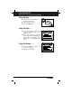
You Can Do It! EASY TO USE - EASY TO VIEW - EASY TO DEFINE Easy To Use . . . . ■ Connect the Code Reader to the vehicle’s test connector. ■ Turn the ignition key "On.” ■ Press the LINK button. Easy To View . . . . ■ The Code Reader retrieves stored codes, Freeze Frame data and I/M Readiness status. ■ Codes, I/M Readiness status and Freeze Frame data are displayed on the Code Reader’s LCD display screen. System status is indicated by LED indicators. Easy To Define . . . .
Safety Precautions SAFETY FIRST! SAFETY FIRST! To avoid personal injury, instrument damage and/or damage to your vehicle; do not use the CAN OBD2 Code Reader before reading this manual. This manual describes common test procedures used by experienced service technicians. Many test procedures require precautions to avoid accidents that can result in personal injury, and/or damage to your vehicle or test equipment.
Safety Precautions SAFETY FIRST! To prevent damage to the on-board computer when taking vehicle electrical measurements, always use a digital multimeter with at least 10 megOhms of impedance. Fuel and battery vapors are highly flammable. To prevent an explosion, keep all sparks, heated items and open flames away from the battery and fuel / fuel vapors. DO NOT SMOKE NEAR THE VEHICLE DURING TESTING. Don't wear loose clothing or jewelry when working on an engine.
About the Code Reader VEHICLES COVERED VEHICLES COVERED The CAN OBD2 Code Reader is designed to work on all OBD 2 compliant vehicles. All 1996 and newer vehicles (cars and light trucks) sold in the United States are OBD 2 compliant. Federal law requires that all 1996 and newer cars and light trucks sold in the United States must be OBD 2 compliant; this includes all Domestic, Asian and European vehicles. Some 1994 and 1995 vehicles are OBD 2 compliant.
About the Code Reader VEHICLES COVERED / BATTERY REPLACEMENT On some Asian and European vehicles the DLC is located behind the “ashtray” (the ashtray must be removed to access it) or on the far left corner of the dash. If the DLC cannot be located, consult the vehicle’s service manual for the location. BATTERY REPLACEMENT 1. Locate the battery cover on the back of the Code Reader. 2. Slide the battery cover off (use your fingers). 3.
About the Code Reader ADJUSTMENTS AND SETTINGS ADJUSTMENTS AND SETTINGS The CAN OBD2 Code Reader lets you make several adjustments and settings to configure the Code Reader for your particular needs. The following adjustments and settings can be made: ■ Adjust Brightness: Adjusts the brightness of the LCD display screen. ■ Demo Mode: Sample data kept in the Code Reader’s memory to use as examples and for demonstration purposes.
About the Code Reader ADJUSTMENTS AND SETTINGS 3. Press the DOWN button to increase the brightness of the LCD display (make the display lighter). 4. When the desired brightness is obtained, press the ENTER/FF button to save your changes and return to the MENU. Selecting the Display Language 1. Use the UP and DOWN buttons, as necessary, to highlight Select Language in the MENU, then press the ENTER/FF button. ■ The Select Language screen displays. ■ The currently selected Language is highlighted.
About the Code Reader ADJUSTMENTS AND SETTINGS Demo Mode 1. Use the UP and DOWN buttons, as necessary, to highlight Demo Mode in the MENU, then press the ENTER/FF button. 2. The Code Reader enters the Demo Mode. 3. Demo Mode demonstrates examples of Generic and Enhanced (Manufacturer Speciific) Diagnostic Trouble Codes, code definitions, Freeze Frame data and I/M Readiness status. ■ Use Demo Mode to familiarize yourself with Code Reader operation, vehicle diagnostic data and/or for demonstration purposes.
Code Reader Controls CONTROLS AND INDICATORS CONTROLS AND INDICATORS 11 10 7 6 8 9 1 3 2 4 5 Figure 1. Controls and Indicators See Figure 1 for the locations of items 1 through 11, below. 1. ERASE button - Erases Diagnostic Trouble Codes (DTCs), and “Freeze Frame” data from your vehicle’s computer, and resets Monitor status. 2. DTC SCROLL button - Displays the DTC View screen and/or scrolls the LCD display to view DTCs when more than one DTC is present. 3.
Code Reader Controls CONTROLS AND INDICATORS 5. DOWN button - When in MENU mode, scrolls DOWN through the menu and submenu selection options. When retrieving and viewing DTCs, scrolls down through the current display screen to display any additional data. 6. UP button - When in MENU mode, scrolls UP through the menu and submenu selection options. When retrieving and viewing DTCs, scrolls ups through the current display screen to display any additional data. 7.
Code Reader Controls DISPLAY FUNCTIONS DISPLAY FUNCTIONS 2 1 10 11 12 3 4 5 6 14 15 7 13 8 9 Figure 2. Display Functions See Figure 2 for the locations of items 1 through 16, below. 1. I/M MONITOR STATUS field - Identifies the I/M Monitor status area. 2. Monitor icons - Indicate which Monitors are supported by the vehicle under test, and whether or not the associated Monitor has run its diagnostic testing (Monitor status).
Code Reader Controls DISPLAY FUNCTIONS 8. Test Data Display Area - Displays DTC definitions, Freeze Frame data, and other pertinent test information messages. 9. MIL icon - Indicates the status of the Malfunction Indicator Lamp (MIL). The MIL icon is visible only when a DTC has commanded the MIL on the vehicle’s dashboard to light. 10. CODE icon - Identifies the Code Number Sequence display area. 11. PENDING icon - Indicates the currently displayed DTC is a “Pending” code. 12.
Onboard Diagnostics COMPUTER ENGINE CONTROLS COMPUTER ENGINE CONTROLS The Introduction of Electronic Engine Controls Electronic Computer Control Systems make it possible for vehicle manufacturers to comply with the tougher emissions and fuel efficiency standards mandated by State and Federal Governments.
Onboard Diagnostics COMPUTER ENGINE CONTROLS The Basic Engine Computer Control System The Computer Control System consists of an on-board computer and several related control devices (sensors, switches, and actuators). The on-board computer is the heart of the Computer Control System. The computer contains several programs with preset reference values for air/fuel ratio, spark or ignition timing, injector pulse width, engine speed, etc.
Onboard Diagnostics COMPUTER ENGINE CONTROLS The computer compares the values received from these sensors with its preset reference values, and makes corrective actions as needed so that the sensor values always match the preset reference values for the current driving condition. The computer makes adjustments by commanding other devices such as the fuel injectors, idle air control, EGR valve or Ignition Module to perform these actions. Vehicle operating conditions are constantly changing.
Onboard Diagnostics COMPUTER ENGINE CONTROLS On-Board Diagnostics - Second Generation (OBD 2) In addition to performing all the functions of the OBD 1 System, the OBD 2 The OBD 2 System is System has been enhanced with new an enhancement of the Diagnostic Programs. These programs OBD 1 System. closely monitor the functions of various emissions-related components and systems (as well as other systems) and make this information readily available (with the proper equipment) to the technician for evaluation.
Onboard Diagnostics COMPUTER ENGINE CONTROLS ■ To use a standardized Diagnostic Link Connector (DLC) in all vehicles. (Before OBD 2, DLCs were of different shapes and sizes.) ■ To standardize the code numbers, code definitions and language used to describe faults. (Before OBD 2, each vehicle manufacturer used their own code numbers, code definitions and language to describe the same faults.) ■ To expand the operation of the Malfunction Indicator Lamp (MIL).
Onboard Diagnostics COMPUTER ENGINE CONTROLS ■ Monitor Has/Has Not Run - The terms “Monitor has run” or “Monitor has not run” are used throughout this manual. “Monitor has run,” means the PCM has commanded a particular Monitor to perform the required diagnostic testing on a system to ensure the system is operating correctly (within factory specifications).
Onboard Diagnostics DIAGNOSTIC TROUBLE CODES (DTCs) DIAGNOSTIC TROUBLE CODES (DTCs) Diagnostic Trouble Codes (DTCs) are meant to guide you to the proper service procedure in the vehicle’s service manual. DO NOT replace parts based only on DTCs without first consulting the vehicle’s service manual for proper testing procedures for that particular system, circuit or component. Diagnostic Trouble Codes (DTCs) are codes that identify a specific problem area.
Onboard Diagnostics DIAGNOSTIC TROUBLE CODES (DTCs) OBD 2 DTC EXAMPLE P0201 - Injector Circuit Malfunction, Cylinder 1 B C P U - Body Chassis Powertrain Network 0 1 2 3 - Generic Manufacturer Specific Generic Includes both Generic and Manufacturer Specific Codes P0201 Identifies the system where the problem is located: 1 - Fuel and Air Metering 2 - Fuel and Air Metering (injector circuit malfunction only) 3 - Ignition System or Misfire 4 - Auxiliary Emission Control System 5 - Vehicle Speed Control
Onboard Diagnostics DIAGNOSTIC TROUBLE CODES (DTCs) There are two types of DTCs used for emissions-related faults: Type “A” and Type “B.” Type “A” codes are “One-Trip” codes; Type “B” DTCs are usually Two-Trip DTCs. When a Type “A” DTC is found on the First Trip, the following events take place: ■ The computer commands the MIL “On” when the failure is first found. ■ If the failure causes a severe misfire that may cause damage to the catalytic converter, the MIL “flashes” once per second.
Onboard Diagnostics OBD 2 MONITORS After the MIL has been turned off, DTCs, Freeze Frame data, and manufacturer-specific enhanced data stay in the computer’s memory. Most of the enhanced data can only be retrieved with special equipment such as a Scan Tool. ■ Erasing the DTCs from the computer’s memory can also turn off the MIL. See ERASING DIAGNOSTIC TROUBLE CODES (DTCs) on page 41, before erasing codes from the computer’s memory.
Onboard Diagnostics OBD 2 MONITORS Oxygen Sensor Monitor Oxygen Sensor Heater Monitor Catalyst Monitor Heated Catalyst Monitor EGR System Monitor EVAP System Monitor Secondary Air System Monitor Air Conditioning (A/C) Monitor The following provides a brief explanation of the function of each Monitor: Comprehensive Component Monitor (CCM) - This Monitor continuously checks all inputs and outputs from sensors, actuators, switches and other devices that provide a signal to the computer.
Onboard Diagnostics OBD 2 MONITORS Misfire Monitor - This Monitor continuously checks for engine misfires. A misfire occurs when the air-fuel mixture in the cylinder does not ignite. The misfire Monitor uses changes in crankshaft speed to sense an engine misfire. When a cylinder misfires, it no longer contributes to the speed of the engine, and engine speed decreases each time the affected cylinder(s) misfire.
Onboard Diagnostics OBD 2 MONITORS Heated Catalyst Monitor - Operation of the “heated” catalytic converter is similar to the catalytic converter. The main difference is that a heater is added to bring the catalytic converter to its operating temperature more quickly. This helps reduce emissions by reducing the converter’s down time when the engine is cold.
Onboard Diagnostics OBD 2 MONITORS Air Conditioning (A/C) Monitor - The A/C Monitor senses leaks in air conditioning systems that utilize R-12 refrigerant. Vehicle manufacturers have been given two options: 1. Use R-12 refrigerant in their A/C systems, and integrate an A/C Monitor in the OBD 2 systems of these vehicles to detect for refrigerant leaks; or 2. Use R-134 refrigerant instead of R12. The A/C Monitor is not required on these vehicles.
Onboard Diagnostics OBD 2 MONITORS The oxygen sensor must reach a temperature of at least 600-650°F, and the engine must reach normal operating temperature, for the computer to enter into closed-loop operation. The oxygen sensor only functions when the computer is in closed-loop. A properly operating oxygen sensor reacts quickly to any change in oxygen content in the exhaust stream. A faulty oxygen sensor reacts slowly, or its voltage signal is weak or missing. The oxygen sensor is a “Two-Trip” monitor.
Onboard Diagnostics OBD 2 MONITORS OBD 2 Reference Table The table below lists current OBD 2 Monitors, and indicates the following for each Monitor: A. Monitor Type (how often does the Monitor run; Continuous or Once per trip) B. Number of trips needed, with a fault present, to set a pending DTC C. Number of consecutive trips needed, with a fault present, to command the MIL “On” and store a DTC D. Number of trips needed, with no faults present, to erase a Pending DTC E.
Preparation for Testing PRELIMINARY VEHICLE DIAGNOSIS WORKSHEET PRELIMINARY VEHICLE DIAGNOSIS WORKSHEET The purpose of this form is to help you gather preliminary information on your vehicle before you retrieve codes. By having a complete account of your vehicle's current problem(s), you will be able to systematically pinpoint the problem(s) by comparing your answers to the fault codes you retrieve.
Preparation for Testing PRELIMINARY VEHICLE DIAGNOSIS WORKSHEET WHEN DID YOU FIRST NOTICE THE PROBLEM: ❑ ❑ ❑ ❑ Just Started Started Last Week Started Last Month Other: LIST ANY REPAIRS DONE IN THE PAST SIX MONTHS: PROBLEMS STARTING ❑ No symptoms ❑ Will not crank ❑ Cranks, but will not start ❑ Starts, but takes a long time ENGINE QUITS OR STALLS ❑ No symptoms ❑ Right after starting ❑ When shifting into gear ❑ During steady-speed driving ❑ ❑ ❑ ❑ IDLING CONDITIONS ❑ No symptoms ❑ Is too slow at all tim
Preparation for Testing PRELIMINARY VEHICLE DIAGNOSIS WORKSHEET AUTOMATIC TRANSMISSION PROBLEMS (if applicable) ❑ No symptoms ❑ Vehicle does not move when in gear ❑ Shifts too early or too late ❑ Jerks or bucks ❑ Changes gear incorrectly PROBLEM OCCURS ❑ Morning ❑ Afternoon ❑ Anytime ENGINE TEMPERATURE WHEN PROBLEM OCCURS ❑ Cold ❑ Warm ❑ Hot DRIVING CONDITIONS WHEN PROBLEM OCCURS ❑ Short - less than 2 miles ❑ With headlights on ❑ 2 - 10 miles ❑ During acceleration ❑ Long - more than 10 miles ❑ Mostly
Preparation for Testing BEFORE YOU BEGIN BEFORE YOU BEGIN The CAN OBD2 Code Reader aids in monitoring electronicand emissions-related faults in your vehicle and retrieving fault codes related to malfunctions in these systems. Mechanical problems such as low oil level or damaged hoses, wiring or electrical connectors can cause poor engine performance and may also cause a fault code to set. Fix any known mechanical problems before performing any test.
Preparation for Testing VEHICLE SERVICE MANUALS VEHICLE SERVICE MANUALS Always refer to the manufacturer’s service manual for your vehicle before performing any test or repair procedures. Contact your local car dealership, auto parts store or bookstore for availability of these manuals.
Using the Code Reader CODE RETRIEVAL PROCEDURE CODE RETRIEVAL PROCEDURE Retrieving and using Diagnostic Trouble Codes (DTCs) for troubleshooting vehicle operation is only one part of an overall diagnostic strategy. Never replace a part based only on the DTC definition. Each DTC has a set of testing procedures, instructions and flow charts that must be followed to confirm the location of the problem. This information is found in the vehicle's service manual.
Using the Code Reader CODE RETRIEVAL PROCEDURE ■ If the unit does not power on automatically when connected to the vehicle’s DLC connector, it usually indicates there is no power present at the vehicle’s DLC connector. Check your fuse panel and replace any burned-out fuses. ■ If replacing the fuse(s) does not correct the problem, consult your vehicle’s repair manual to identify the proper computer (PCM) fuse/ circuit, and perform any necessary repairs before proceeding. 5. Turn the ignition on.
Using the Code Reader CODE RETRIEVAL PROCEDURE ■ The Code Reader will automatically re-link to the vehicle’s computer every 15 seconds to refresh the data being retrieved. When data is being refreshed, the message “One moment Auto – link in progress” is shown on the LCD display. This action repeats as long as the Code Reader is communicating with the vehicle’s computer. ■ The Code Reader will display a code only if codes are present in the vehicle’s computer memory.
Using the Code Reader CODE RETRIEVAL PROCEDURE In the case of long code definitions, or when viewing Freeze Frame data, a small arrow is shown in the upper/lower right-hand corner of the code display area to indicate the presence of additional information. Use the and buttons, as necessary, to view the additional information. 9. Read and interpret Diagnostic Trouble Codes/system condition using the LCD display and the green, yellow and red LEDs.
Using the Code Reader CODE RETRIEVAL PROCEDURE ■ Red LED – Indicates there is a problem with one or more of the vehicle’s systems. The red LED is also used to indicate that DTC(s) are present (displayed on the Code Reader’s screen). In this case, the Multifunction Indicator (Check Engine) lamp on the vehicle’s instrument panel will be illuminated. On some vehicle models, the computer will store nonemission related DTCs. These DTCs will not command the MIL on since they are not emission related.
Using the Code Reader CODE RETRIEVAL PROCEDURE 11. Freeze Frame Data (if available) can be viewed at any time (except MENU mode) by pressing the ENTER/FF button. ■ In OBD2 systems, when an emissions-related engine malfunction occurs that causes a DTC to set, a record or snapshot of engine conditions at the time that the malfunction occurred is also saved in the vehicle’s computer memory. The record saved is called Freeze Frame data.
Using the Code Reader ERASING DIAGNOSTIC TROUBLE CODES (DTCs) ■ To prolong battery life, the Code Reader automatically shuts “Off” approximately three minutes after it is disconnected from the vehicle. The DTCs retrieved, Monitor Status and Freeze Frame data (if any) will remain in the Code Reader’s memory, and may be viewed at any time by turning the unit “On”.
Using the Code Reader I/M READINESS TESTING 3. Press and release the ERASE button. A confirmation message shows on the LCD display. - If you are sure you want to proceed press the ERASE button again to erase DTCs from the vehicle’s computer. - If you do not want to continue with the erase process, press the POWER/LINK button to exit the erase mode. 4. If you chose to erase DTCs, a progress screen displays while the erase function is in progress.
Using the Code Reader I/M READINESS TESTING Emissions tests vary depending on the geographic or regional area in which the vehicle is registered. If the vehicle is registered in a highly urbanized area, the I/M 240 is probably the type of test required. If the vehicle is registered in a rural area, the stricter “dynamometer type” test may not be required.
Using the Code Reader I/M READINESS TESTING Emissions Inspection and Maintenance (I/M) Readiness Monitor Status Information I/M Readiness Monitor Status shows which of the vehicle's Monitors have run and completed their diagnosis and testing, and which ones have not yet run and completed testing and diagnosis of their designated sections of the vehicle's emissions system.
Using the Code Reader I/M READINESS TESTING 3. Other areas may only require that some (but not all) Monitors indicate a "Has Run" status before an Emissions Test (Smog Check) may be performed. Monitors with a "Has Run" status indicate that all the required conditions they needed to perform diagnosis and testing of their assigned engine area (system) have been met, and all diagnostic testing has completed successfully.
Using the Code Reader I/M READINESS TESTING ■ If the illumination of the Yellow LED is being caused by monitors that “have not run” their diagnostic testing, then the issue of the vehicle being ready for an Emissions Test (Smog Check) depends on the emissions regulations and laws of your local area. - Some areas require that all Monitors indicate a "Has Run" status before they allow an Emissions Test (Smog Check) to be performed.
Using the Code Reader I/M READINESS TESTING On some vehicle models, the computer will store nonemission related DTCs. These DTCs will not command the MIL on since they are not emission related. If the Code Reader retrieves one of these types of codes, the MIL will not be commanded on, and the Yellow LED on the Code Reader will be iluminated. In most cases, these types of codes will not prevent the Emissions Test from being performed.
Using the Code Reader I/M READINESS TESTING If the vehicle needs to be driven in order to perform a Trip Drive Cycle, ALWAYS have a second person help you. One person should drive the vehicle while the other person observes the Monitor icons on the Code Reader for Monitor RUN status. Trying to drive and observe the Code Reader at the same time is dangerous, and could cause a serious traffic accident. 4.
Glossary GLOSSARY OF TERMS AND ABBREVIATIONS INTRODUCTION This Glossary contains definitions for abbreviations and terms you may find in this manual or in your vehicle service manual.
Glossary GLOSSARY OF TERMS AND ABBREVIATIONS Manufacturer Specific Code – A DTC that applies only to OBD 2 compliant vehicles made by a specific manufacturer. MIL – Malfunction Indicator Lamp (also referred to as “Check Engine” light OBD 1 – On-Board Diagnostics Version 1 (also referred to as “OBD I”) OBD 2 – On-Board Diagnostics Version 2 (also referred to as “OBD II”) On-Board Computer – The central processing unit in the vehicle’s computer control system.
Warranty and Servicing LIMITED ONE YEAR WARRANTY The Manufacturer warrants to the original purchaser that this unit is free of defects in materials and workmanship under normal use and maintenance for a period of one (1) year from the date of original purchase. If the unit fails within the one (1) year period, it will be repaired or replaced, at the Manufacturer’s option, at no charge, when returned prepaid to the Service Center with Proof of Purchase. The sales receipt may be used for this purpose.
Notes CAN OBD2 E
Notes CAN OBD2 E
® Innova Electronics Corp. 17291 Mt.