GM CODE READER 1.
Table of Contents Paragraph Title Page No. YOU CAN DO IT! ........................................................ ii GENERAL INFORMATION 1.1 1.2 1.3 1.4 1.5 1.6 YOUR VEHICLE'S COMPUTER SYSTEM ............... ABOUT YOUR CODE READER................................. TEST CONNECTOR LOCATIONS ............................ SAFETY PRECAUTIONS ........................................... VEHICLE SERVICE MANUALS ............................... PRELIMINARY VEHICLE DIAGNOSIS ..................
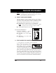
1 1 2 3 GM • Test connector usually found under the left side of the dashboard. • Set Selector switch to ECM A-B position. • Make sure ignition is off. Plug Code Reader into test connector. • Turn on ignition. DO NOT START ENGINE. • Read codes from flashing "Check Engine" or "Service Engine Soon" light. Pinpoint Problems • Locate fault code(s) in the appropriate Service Codes List.
1 1.1 YOUR VEHICLE'S COMPUTER SYSTEM Today's vehicles are equipped with computer self-testing abilities that can locate problems in your vehicle and store them as service codes in the vehicle's onboard computer. The Code Reader allows you access to the computer's memory and recalls the service codes. 1.1.1 Instrument Panel Indicator Lights Your vehicle's Instrument panel has several indicator lights, such as the "Check Engine", "Service Engine Soon", "ABS", "Shift to D2" and "Temperature" indicator lights.
General Information NOTE : For Saturn vehicles, either the "Shift to D2" light or the "Temperature" indicator light is used to transmit Saturn Electronic Transmission codes. 1.2 ABOUT YOUR CODE READER The Code Reader is a device which connects to your vehicle's computer self-test connector. It allows the computer to output the service codes through the vehicle's instrument panel indicator lights.
1 1.4 SAFETY PRECAUTIONS • Always observe safety precautions whenever working on a vehicle. a. b. c. Always wear safety eye protection. Only work on your vehicle in a well-ventilated area. Put transmission in “park” (for automatic) or “neutral” (for manual). Set parking brake. Put blocks on drive wheels. Avoid moving fan blades or any potentially moving parts. Avoid hot engine parts. Turn off ignition before connecting (or disconnecting) any testing equipment.
General Information 1.6 PRELIMINARY VEHICLE DIAGNOSIS WORKSHEET The purpose of this form is to help you gather preliminary information on your vehicle before you retrieve codes. By having a complete account of your vehicle's current problem(s), you will be able to systematically pinpoint the problem(s) by comparing your answers to the fault codes you retrieve. You can also provide this information to your mechanic to assist in diagnosis and help avoid costly and unnecessary repairs.
1 WHEN DID YOU FIRST NOTICE THE PROBLEM: ❑ ❑ ❑ ❑ Just Started Started Last Week Started Last Month Other: LIST ANY REPAIRS DONE IN THE PAST SIX MONTHS: PROBLEMS STARTING ❑ No symptoms ❑ Will not crank ❑ Cranks, but will not start ❑ Starts, but takes a long time ENGINE QUITS OR STALLS ❑ No symptoms ❑ Right after starting ❑ When shifting into gear ❑ During steady-speed driving ❑ ❑ ❑ ❑ IDLING CONDITIONS ❑ No symptoms ❑ Is too slow at all times ❑ Is too fast ❑ Is sometimes too fast or too slow ❑ Is roug
General Information AUTOMATIC TRANSMISSION PROBLEMS (if applicable) ❑ No symptoms ❑ Vehicle does not move when in ❑ Shifts too early or too late gear ❑ Changes gear incorrectly ❑ Jerks or bucks PROBLEM OCCURS ❑ Morning ❑ Afternoon ❑ Anytime ENGINE TEMPERATURE WHEN PROBLEM OCCURS ❑ Cold ❑ Warm ❑ Hot DRIVING CONDITIONS WHEN PROBLEM OCCURS ❑ Short - less than 2 miles ❑ With headlights on ❑ 2 ~ 10 miles ❑ During acceleration ❑ Long - more than 10 miles ❑ Mostly driving downhill ❑ Stop and go ❑ Mostly driv
2 2.1 VEHICLES COVERED This Code Reader may be used to retrieve engine service codes from most General Motors (GM) and Saturn domestic cars and trucks (EXCEPT Geo, Nova, and Sprint). Includes all models EXCEPT Cadillacs and diesel vehicles. Specific makes and models are listed below.
Retrieving ECM Codes Model Year 1995 Make Model Chevrolet Caprice 4.3 liter Saturn All models Trucks and Vans All one ton capacity or less with gas engines (EXCEPT S/T Series vehicles) * Not applicable to models equipped with climate control computers NOTE: For 1994 and 1995 vehicles, only the models listed above are compatible with the Code Reader. The Code Reader is not compatible with 1996 and later model year vehicles. 2.1.
2 Please read your vehicle’s service manual for proper connection of vacuum hoses, electrical wiring, and wiring harness connectors. Check the following areas: a. All fluid levels b. Air cleaner and ducts c. Belts d. Mechanical linkage associated with sensor e. Vacuum hoses f. Spark plugs and wires g. Electrical wiring h. i. j. Electrical connectors Proper battery voltage Fuel system components 2.
Retrieving ECM Codes • Each code is transmitted three times before the next code is sent. • Code sets will begin with Code 12 ("System Pass") even if fault codes are present. • The codes will continue to be sent as long as the ignition is on and the Code Reader is connected. • • Count blinks to get the service codes: Code 12 looks like: = Code 12 PAUSE BLINK BLINK Code 12 is not a fault code. Code 12 indicates the computer's self-diagnostic system is functioning properly (SYSTEM PASS).
2 NOTE: ■ 8. If "Service Engine Soon" light does not turn on, the initial stored fault codes were all "intermittent" fault codes. (Refer to the "Diagnostic Procedures" section in the manufacturer's service manual for your vehicle.) Follow the testing and repair procedures outlined in the manufacturer's service manual for your vehicle to correct "hard" faults.
Retrieving ECM Codes will still affect it) before retrieving trouble codes. Refer to your vehicle's service/repair manual for specifications and system testing procedures which apply to your particular vehicle. 2.4 ERASING SERVICE CODES • Always observe safety precautions before and during testing process. 1. Turn off ignition. 2. Remove ECM fuse from the fuse block or disconnect the negative battery cable to disconnect power to the vehicle's computer. 3.
2 2.5.
Retrieving ECM Codes CODE SERVICE CODE DEFINITION 24 Vehicle speed sensor (VSS) - open or short circuit problems or park/neutral switch circuit problem 25 Manifold air temperature (MAT) sensor - signal voltage is low or high Vacuum switching valve circuit open or shorted to ground ATS sensor - signal voltage is high or low 26 Quad-Driver module or Quad-driver No. 1 error 27 2nd gear switch problem Quad-Driver module or Quad-driver No.
2 CODE SERVICE CODE DEFINITION 33 Mass air flow (MAF) sensor - signal voltage or frequency is high during engine idle Manifold absolute pressure (MAP) sensor - signal voltage is high during engine idle (Note: Engine misfire or unstable idle may cause this code) 34 Mass air flow (MAF) sensor - signal voltage or frequency is low during engine cruise Manifold absolute pressure (MAP) sensor - signal voltage is low during ignition on Pressure sensor circuit - signal voltage too high or low (carburetor engin
Retrieving ECM Codes CODE SERVICE CODE DEFINITION 42 Electronic spark timing (EST) circuit - open or shorted Direct ignition system (DIS) fault - bypass circuit open or shorted to ground during engine run Fuel cutoff relay circuit - open or shorted to ground 43 Electronic spark timing (EST) circuit - low voltage detected Electronic spark control (ESC) - circuit problems 44 Lean exhaust indicated (Left side on dual oxygen models) 45 Rich exhaust indicated (Left side on dual oxygen models) 46 Vehic
2 CODE SERVICE CODE DEFINITION 56 Vacuum sensor circuit fault or quad driver "B" fault (3.8L VIN1) Corrosivity/add coolant 57 Boost control problem (3.8L VIN1) 58 Vehicle Anti-Theft System fault (3.
Retrieving ECM Codes CODE SERVICE CODE DEFINITION 68 On-board cruise control switch circuit problems Servo Position Sensor (SPS) circuit fault or shorted A/C clutch relay circuit (Corvette) or overdrive ratio error 69 Air conditioning head pressure switch circuit fault or air conditioning pressure switch problem Torque converter clutch stuck "on" 70 Air conditioning refrigerant pressure sensor circuit fault (high pressure) or quad driver module error 71 Air conditioning evaporator temperature senso
2 CODE SERVICE CODE DEFINITION 82 Internal PCM communication fault (Saturn) or QDM Solenoid "A" monitored voltage differs from commanded Ignition system fault - 3X signal problem 83 Torque Converter Clutch (TCC) solenoid - circuit problems Reverse Inhibit - open or short circuit in reverse inhibit solenoid 84 3-2 Control solenoid - open or short circuit problems Skip shift solenoid - open or short circuit problems 85 Programmable Read Only Memory error or undefined gear ratio (input or output senso
Retrieving ECM Codes 2.5.2 Saturn Electronic Transmission Service Codes • Transmission codes will be transmitted (if present) after all engine codes are transmitted and code 11 has been sent. Code 11 indicates that transmission codes are present and will be transmitted on the "Shift to D2" light (1991-92 models) or the "Temperature" indicator light (1993 and later models).
2 CODE SERVICE CODE DEFINITION 48 Hold mode voltage is too low Reference input intermittent 49 Gear selector error signal 51 Powertrain Control Module (PCM) computer circuit problem 52 Hold mode stuck "on" Battery voltage out of range 53 Hold mode stuck "off" ESC (Knock present) 54 Powertrain Control Module (PCM) computer circuit problem 5-volt reference ground 55 Transaxle temperature sensor failure 56 Generic Field-Effect Transistor (FET) driver failure 57 Powertrain Control Module (PCM
Retrieving ECM Codes CODE SERVICE CODE DEFINITION 73 3rd line circuit - grounded or open Coolant sensor signal unstable 74 Coolant/Transmission temperature sensor ratio error 3rd line circuit - shorted 75 3rd gear stuck "on" Air temperature sensor signal 76 4th line circuit - grounded or open Throttle position sensor (TPS) to manifold absolute pressure (MAP) sensor voltage out of range 77 4th line circuit - shorted 78 4th gear stuck "on" 79 Torque Converter Clutch (TCC) circuit - grounded or
3 3.1 ANTILOCK BRAKE SYSTEMS (ABS) 3.1.1 What is ABS? The ABS system utilizes several mechanical, hydraulic, and electric/electronic components to automatically control hydraulic brake pressure to the rear, or front and rear wheels (depending on the brake system) to prevent wheel lock-up during hard braking. 3.1.
Retrieving ABS Codes Year Model ABS Type 1989-93 Astro, "G" Series Van, "R" and "V" Series Kelsey-Hayes Trucks, Safari, Suburban RWAL 1987-94 Blazer, "C" and "K" Series Pickup, Sierra, Kelsey-Hayes "S" and "T" Series Pickup (EXCEPT RWAL 93-94 4.
3 2. After retrieving ABS fault codes, erase codes using the appropriate procedures for your vehicle and ABS system (paragraph 3.4). 3. Repeat the procedure to retrieve ABS fault codes (step 1, above). NOTE: It may be necessary to perform a thorough test drive to reset some fault codes. 4. In most cases, codes which reappear indicate "hard" faults. Codes which DO NOT reappear are usually "intermittent" faults. 5.
Retrieving ABS Codes • • • All codes are two digits. • Second digit of service code is followed by a termination code ("Anti-Lock" light remains steady on). Count blinks to get the service codes: First and second digits of code are separated by a 3 second pause. NOTE: • DO NOT count termination code as part of second digit. Code 13 looks like: PAUSE BLINK 7. BLINK = Code 13 BLINK TERMINATION CODE Up to seven codes can be stored by the EBCM.
3 • • • Count blinks to get the service codes. • Code 3 looks like: Codes may be one or two digits. Codes are displayed as a pattern of one long blink followed by one or more short blinks. Count ALL blinks to get code. = Code 3 LONG BLINK SHORT BLINK SHORT BLINK • The EBCM stores only one service code at a a time, even though it may detect more than one fault condition. The first fault detected results in a stored service code.
Retrieving ABS Codes • Code 21 looks like: = Code 21 PAUSE BLINK NOTE: 6. BLINK BLINK Service codes will repeat as long as Code Reader is connected. Turn off ignition and remove the Code Reader. 3.3.4 Retrieving Service Codes for Bosch 2S and 2U Systems 1. Turn off ignition. 2. Connect the Code Reader to the vehicle test connector. NOTE: The Code Reader only fits into the connector one way. 3. Set Selector Switch to ABS A-H position. 4. Turn on ignition. DO NOT START THE ENGINE. 5.
3 3.4 ERASING SERVICE CODES • Always observe safety precautions before and during testing process. • Erase codes only when all repairs have been completed. Determine your vehicle's ABS Type (paragraph 3.2) and erase codes using the appropriate procedures: 3.4.1 3.4.2 3.4.3 3.4.4 3.4.5 Teves II Kelsey-Hayes RWAL Kelsey-Hayes 4WAL Bosch 2S Bosch 2U 3.4.1 Erasing Service Codes for Teves II Systems 1. Drive vehicle at a speed greater than 20 MPH. Service codes will automatically be cleared. 2.
Retrieving ABS Codes 5. Connect the Code Reader to the vehicle test connector for one second, remove the Code Reader for one second, reconnect the Code Reader for one second, then remove the Code Reader. 6. Turn off ignition. 7. Reinstall STOP/HAZARD fuse in fuse block. 8. Repeat procedure for retrieving service codes (paragraph 3.3.2) to make sure codes have been erased. 3.4.3 Erasing Service Codes for Kelsey-Hayes 4WAL Systems 1. Turn on ignition. 2. Set Selector Switch to ABS A-H position. 3.
3 7. The ""Service ABS" light should display code 12 continuously. If any other codes are displayed, repeat steps 1 through 6. 8. Turn off ignition. 3.4.5 Erasing Service Codes for Bosch 2U Systems 1. Turn on ignition and observe "Anti-Lock" light. "AntiLock" light should turn off within 3 to 4 seconds. If "AntiLock" light remains on, a fault is still present. NOTE: Service codes cannot be erased until all stored service codes have been retrieved. 2. Set Selector Switch to ABS A-H position. 3.
Retrieving ABS Codes 3.5.
3 Code Service Code Definition 61 Electronic Brake Control Module loop circuit 71 Left front outlet valve 72 Right front outlet valve 73 Rear outlet valve 74 Rear outlet valve 75 Left front Wheel Speed Sensor 76 Right front Wheel Speed Sensor 77 Right rear Wheel Speed Sensor 78 Left rear Wheel Speed Sensor 3.5.
Retrieving ABS Codes 3.5.
3 Code Service Code Definition 55 4 Wheel Anti-Lock (4WAL) control unit fault 56 4 Wheel Anti-Lock (4WAL) control unit fault 57 4 Wheel Anti-Lock (4WAL) control unit fault 58 4 Wheel Anti-Lock (4WAL) control unit fault 59 4 Wheel Anti-Lock (4WAL) control unit fault 60 4 Wheel Anti-Lock (4WAL) control unit fault 61 4 Wheel Anti-Lock (4WAL) control unit fault 62 4 Wheel Anti-Lock (4WAL) control unit fault 63 4 Wheel Anti-Lock (4WAL) control unit fault 64 4 Wheel Anti-Lock (4WAL) control u
Retrieving ABS Codes Code Service Code Definition 41 Right front solenoid valve fault 45 Left front solenoid valve fault 55 Rear solenoid valve fault 61 Pump motor or motor relay fault 63 Solenoid valve relay fault 71 Electronic Brake Control Module (EBCM) fault 72 Serial data link fault 75 Lateral accelerometer fault; short to battery, ground or open circuit 76 Lateral accelerometer fault, signal out of range or incorrect 3.5.
4 4.1 INTRODUCTION The Society of Automotive Engineers has issued a Standard (SAE J1930) for Electrical/Electronic Systems Diagnostic Terms, Definitions, Abbreviations, and Acronyms. However, at the present time, this Standard is not in wide use by vehicle manufacturers. This Glossary contains definitions for abbreviations and terms you may find in this manual or in your vehicle service manual. These definitions may not agree with those contained in SAE J1930. 4.
Glossary BAC – Bypass Air Control valve. BARO – Barometric Pressure. BASE IDLE – Idle rpm determined by throttle switch with idle speed control fully retracted. BCM – Body Computer Module. BOO – Brake On-Off input to the computer. BOOST – Turbo charger boost solenoid or its control circuit. BP – Barometric Pressure sensor. Used to compensate for altitude variations. BPMV – Brake Pressure Modulator Valve. BTDC – Before Top Dead Center. BVT – Back-pressure Variable Transducer.
4 CHECK VALVE – Valve that operates like a one-way gate. CID – Cylinder Identification sensor or its circuit. CKT – Circuit. CL – Closed Loop. CLC – Converter Lock-up Clutch. CO – Carbon Monoxide. COC – Conventional Oxidation Catalyst. COMPUTER TIMING –Total spark advance in degrees before top dead center. CPS – Crankshaft Position Sensor. Provides the ECU with engine speed and crankshaft angle (position). CRT – Cathode Ray Tube. A device for displaying video signals, similar to a television picture tube.
Glossary DUAL CATALYTIC CONVERTER – Combines 2 converters in one shell. Controls NOx, HC and CO. Also called TWC. DV TW – Delay Valve, 2 Way. DVM (10 MEG) – Digital voltmeter with a minimum of 10 million ohms resistance. Allows measurement in circuit without affecting the circuit operation. DWELL – Amount of time (recorded on a dwell meter in degrees) that current passes through a closed switch. EAS – Electronic Air Switching, directs airflow to catalytic converter or exhaust ports of the engine.
4 EMR – Electronic Module Retard, controls spark retard. ENGINE CONTROL MODULE – A microprocessor based device which contains electronic circuitry to control and monitor air/fuel and emission systems, and aid in diagnostics. EPC – Electronic Pressure Control solenoid. EPROM – Erasable Programmable Read Only Memory. ERS – Engine RPM Sensor. ESA – Electronic Spark Advance. ESC – Electronic Spark Control. EST – Electronic Spark Timing. EVP – EGR Valve Position sensor or its circuit.
Glossary HPA - High Pressure Accumulator. IAC – Idle Air Control. IAS – Inlet Air Solenoid valve or its circuit. IAT – Intake air temperature sensor, performs same function as MAT sensor. ICM – Integrated Control Module. IDLE TRACKING SWITCH – An input device that sends a signal to the computer to indicate a closed throttle condition. IGN – Ignition. INTERMITTENT FAULT – Fault which occurred during a previous engine operating cycle.
4 MFI – Multi-port Fuel Injection. MIL – Malfunction Indicator Light. Check engine light. MIXTURE CONTROL SOLENOID – Device installed on carburetor, that regulates the air/fuel ratio. MLP – Manual (shift) Lever Position sensor or its circuit. MPFI – Multi-Port Fuel Injection. MULTI-PORT FUEL INJECTION – Individual injectors for each cylinder mounted in intake manifold. Injectors are pulsed in groups rather than individually. NDS – Neutral Drive Switch. NGS – Neutral Gear Switch or its circuit.
Glossary QUAD-DRIVER (QDM) – Computer chip, in the PCM, capable of operating four separate outputs. Some have digital and some have pulse width modulated outputs. RAP – Retained Accessory Power. RELAY – Switching device operated by a low current circuit, which controls opening and closing of another higher current circuit. RELIEF VALVE – Pressure limiting valve located in exhaust chamber of thermactor air pump. Relieves part of exhaust airflow if pressure exceeds a calibrated value.
4 TDC – Top Dead Center. THERMACTOR AIR CONTROL VALVE – Combines function of a normally closed air bypass valve and an air diverter valve in one integral valve. THERMACTOR AIR SYSTEM – Efficiency of catalytic converter is dependent upon temperature and chemical makeup of exhaust gases. These requirements are met by the thermactor air supply system. THREE-WAY CATALYST – Combines 2 converters in 1 shell. Controls NOx, HC and CO. Also called dual catalytic converter.
Glossary GM 4-10
5 5.1 LIMITED ONE YEAR WARRANTY The Manufacturer warrants to the original purchaser that this unit is free of defects in materials and workmanship under normal use and maintenance for a period of one (1) year from the date of original purchase. If the unit fails within the one (1) year period, it will be repaired or replaced, at the Manufacturer's option, at no charge, when returned prepaid to the Service Center with Proof of Purchase. The sales receipt may be used for this purpose.
Warranty and Service GM 5-2
#3123 INNOVA ELECTRONICS CORPORATION 17287 Mt.