E
Table of Contents Title E Page No. INTRODUCTION What is OBD? . . . . . . . . . . . . . . . . . . . . . . . . . . . . . . . . . . . . . 1 YOU CAN DO IT! . . . . . . . . . . . . . . . . . . . . . . . . . . . . . . . . . . . . . . . 2 SAFETY PRECAUTIONS Safety First! . . . . . . . . . . . . . . . . . . . . . . . . . . . . . . . . . . . . . . 3 ABOUT THE SCAN TOOL Vehicles Covered . . . . . . . . . . . . . . . . . . . . . . . . . . . . . . . . . . Battery Replacement . . . . . . . . . . . . . . . . . .
Introduction WHAT IS OBD? WHAT IS OBD? The OBD2 Scan Tool is designed to work on all OBD 2 compliant vehicles. All 1996 and newer vehicles (cars, light trucks and SUVs) sold in the United States are OBD 2 compliant. One of the most exciting improvements in the automobile industry was the addition of on-board diagnostics (OBD) on vehicles, or in more basic terms, the computer that activates the vehicle’s “CHECK ENGINE” light.
You Can Do It! EASY TO USE - EASY TO VIEW - EASY TO DEFINE Easy To Use . . . . ■ Connect the Scan Tool to the vehicle’s test connector. ■ Turn the ignition key "On.” ■ Press the LINK button. Easy To View . . . . ■ The Scan Tool retrieves stored codes, Freeze Frame data and I/M Readiness status. ■ Codes, I/M Readiness status and Freeze Frame data are displayed on the Scan Tool’s display screen. System status is indicated by LED indicators. Easy To Define . . . .
Safety Precautions SAFETY FIRST! SAFETY FIRST! To avoid personal injury, instrument damage and/or damage to your vehicle; do not use the OBD2 Scan Tool before reading this manual. This manual describes common test procedures used by experienced service technicians. Many test procedures require precautions to avoid accidents that can result in personal injury, and/or damage to your vehicle or test equipment.
Safety Precautions SAFETY FIRST! To prevent damage to the on-board computer when taking vehicle electrical measurements, always use a digital multimeter with at least 10 megOhms of impedance. Fuel and battery vapors are highly flammable. To prevent an explosion, keep all sparks, heated items and open flames away from the battery and fuel / fuel vapors. DO NOT SMOKE NEAR THE VEHICLE DURING TESTING. Don't wear loose clothing or jewelry when working on an engine.
About the Scan Tool VEHICLES COVERED VEHICLES COVERED The OBD2 Scan Tool is designed to work on all OBD 2 compliant vehicles. All 1996 and newer vehicles (cars and light trucks) sold in the United States are OBD 2 compliant. Federal law requires that all 1996 and newer cars and light trucks sold in the United States must be OBD 2 compliant; this includes all Domestic, Asian and European vehicles. Some 1994 and 1995 vehicles are OBD 2 compliant.
About the Scan Tool VEHICLES COVERED / BATTERY REPLACEMENT On some Asian and European vehicles the DLC is located behind the “ashtray” (the ashtray must be removed to access it) or on the far left corner of the dash. If the DLC cannot be located, consult the vehicle’s service manual for the location. BATTERY REPLACEMENT Replace batteries when the battery symbol is visible on display and/or the 3 LEDS are all lit and no other data is visible on screen. 1.
About the Scan Tool ADJUSTMENTS AND SETTINGS ADJUSTMENTS AND SETTINGS The OBD2 Scan Tool lets you make several adjustments and settings to configure the Scan Tool for your particular needs. The following adjustments and settings are available: ■ DTC Library - Library of OBD2 DTC definitions. ■ Adjust Brightness: Adjusts the brightness of the display screen. ■ Display Backlight: Turns the display backlight on and off.
About the Scan Tool ADJUSTMENTS AND SETTINGS ■ The selected character displays “solid”, and the next character begins flashing. 3. Select the remaining characters in the DTC in the same way, pressing the DTC SCROLL button to confirm each character. When you have selected all the DTC characters, press the ENTER/LD button to view the DTC definiition.
About the Scan Tool ADJUSTMENTS AND SETTINGS ■ The Brightness field shows the current brightness setting, from 0 to 43. 2. Press the UP button to decrease the brightness of the display (make the display darker). 3. Press the DOWN button to increase the brightness of the display (make the display lighter). 4. When the desired brightness is obtained, press the ENTER/LD button to save your changes and return to the MENU. Using the Backlight 1.
About the Scan Tool ADJUSTMENTS AND SETTINGS Setting the Unit of Measurement 1. Use the UP and DOWN buttons, as necessary, to highlight Unit of Measurement in the MENU, then press the ENTER/LD button. 2. Press the UP or DOWN button, as necessary, to highlight the desired Unit of Measurement. 3. When the desired Unit of Measurement value is selected, press the ENTER/LD button to save your changes. Exiting the MENU Mode 1.
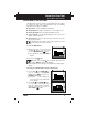
Scan Tool Controls CONTROLS AND INDICATORS CONTROLS AND INDICATORS 11 10 7 6 8 9 1 3 2 4 5 Figure 1. Controls and Indicators See Figure 1 for the locations of items 1 through 11, below. 1. ERASE button - Erases Diagnostic Trouble Codes (DTCs), and “Freeze Frame” data from your vehicle’s computer, and resets Monitor status. 2. DTC SCROLL button - Displays the DTC View screen and/or scrolls the display to view DTCs when more than one DTC is present. 3.
Scan Tool Controls DISPLAY FUNCTIONS 5. DOWN button - When in MENU mode, scrolls DOWN through the menu and submenu selection options. When LINKED to a vehicle, scrolls DOWN through the current display screen to display any additional data. 6. UP button - When in MENU mode, scrolls UP through the menu and submenu selection options. When LINKED to a vehicle, scrolls UP through the current display screen to display any additional data. 7.
Scan Tool Controls DISPLAY FUNCTIONS 1. I/M MONITOR STATUS field - Identifies the I/M Monitor status area. 2. Monitor icons - Indicate which Monitors are supported by the vehicle under test, and whether or not the associated Monitor has run its diagnostic testing (Monitor status). When a Monitor icon is solid, it indicates that the associated Monitor has completed its diagnostic testing.
Scan Tool Controls DISPLAY FUNCTIONS 13. Code Number Sequence - The Scan Tool assigns a sequence number to each DTC that is present in the computer’s memory, starting with “01.” This number indicates which code is currently displayed. Code number “01” is always the highest priority code, and the one for which “Freeze Frame” data has been stored. If “01” is a “Pending” code, there may or may not be “Freeze Frame” data stored in memory. 14.
Onboard Diagnostics DIAGNOSTIC TROUBLE CODES (DTCs) DIAGNOSTIC TROUBLE CODES (DTCs) Diagnostic Trouble Codes (DTCs) are meant to guide you to the proper service procedure in the vehicle’s service manual. DO NOT replace parts based only on DTCs without first consulting the vehicle’s service manual for proper testing procedures for that particular system, circuit or component. Diagnostic Trouble Codes (DTCs) are codes that identify a specific problem area.
Onboard Diagnostics DIAGNOSTIC TROUBLE CODES (DTCs) OBD 2 DTC EXAMPLE P0201 - Injector Circuit Malfunction, Cylinder 1 B C P U - Body Chassis Powertrain Network 0 1 2 3 - Generic Manufacturer Specific Generic Includes both Generic and Manufacturer Specific Codes P0201 Identifies the system where the problem is located: 1 - Fuel and Air Metering 2 - Fuel and Air Metering (injector circuit malfunction only) 3 - Ignition System or Misfire 4 - Auxiliary Emission Control System 5 - Vehicle Speed Control
Preparation for Testing PRELIMINARY VEHICLE DIAGNOSIS WORKSHEET PRELIMINARY VEHICLE DIAGNOSIS WORKSHEET The purpose of this form is to help you gather preliminary information on your vehicle before you retrieve codes. By having a complete account of your vehicle's current problem(s), you will be able to systematically pinpoint the problem(s) by comparing your answers to the fault codes you retrieve.
Preparation for Testing PRELIMINARY VEHICLE DIAGNOSIS WORKSHEET WHEN DID YOU FIRST NOTICE THE PROBLEM: ❑ ❑ ❑ ❑ Just Started Started Last Week Started Last Month Other: LIST ANY REPAIRS DONE IN THE PAST SIX MONTHS: PROBLEMS STARTING ❑ No symptoms ❑ Will not crank ❑ Cranks, but will not start ❑ Starts, but takes a long time ENGINE QUITS OR STALLS ❑ No symptoms ❑ Right after starting ❑ When shifting into gear ❑ During steady-speed driving ❑ ❑ ❑ ❑ IDLING CONDITIONS ❑ No symptoms ❑ Is too slow at all tim
Preparation for Testing PRELIMINARY VEHICLE DIAGNOSIS WORKSHEET AUTOMATIC TRANSMISSION PROBLEMS (if applicable) ❑ No symptoms ❑ Vehicle does not move when in gear ❑ Shifts too early or too late ❑ Jerks or bucks ❑ Changes gear incorrectly PROBLEM OCCURS ❑ Morning ❑ Afternoon ❑ Anytime ENGINE TEMPERATURE WHEN PROBLEM OCCURS ❑ Cold ❑ Warm ❑ Hot DRIVING CONDITIONS WHEN PROBLEM OCCURS ❑ Short - less than 2 miles ❑ With headlights on ❑ 2 - 10 miles ❑ During acceleration ❑ Long - more than 10 miles ❑ Mostly
Preparation for Testing BEFORE YOU BEGIN BEFORE YOU BEGIN The OBD2 Scan Tool aids in monitoring electronic- and emissions-related faults in your vehicle and retrieving fault codes related to malfunctions in these systems. Mechanical problems such as low oil level or damaged hoses, wiring or electrical connectors can cause poor engine performance and may also cause a fault code to set. Fix any known mechanical problems before performing any test.
Preparation for Testing VEHICLE SERVICE MANUALS VEHICLE SERVICE MANUALS Always refer to the manufacturer’s service manual for your vehicle before performing any test or repair procedures. Contact your local car dealership, auto parts store or bookstore for availability of these manuals.
Using the Scan Tool CODE RETRIEVAL PROCEDURE CODE RETRIEVAL PROCEDURE Retrieving and using Diagnostic Trouble Codes (DTCs) for troubleshooting vehicle operation is only one part of an overall diagnostic strategy. Never replace a part based only on the DTC definition. Each DTC has a set of testing procedures, instructions and flow charts that must be followed to confirm the location of the problem. This information is found in the vehicle's service manual.
Using the Scan Tool CODE RETRIEVAL PROCEDURE ■ If the unit does not power on automatically when connected to the vehicle’s DLC connector, it usually indicates there is no power present at the vehicle’s DLC connector. Check your fuse panel and replace any burned-out fuses. ■ If replacing the fuse(s) does not correct the problem, consult your vehicle’s repair manual to identify the proper computer (PCM) fuse/ circuit, and perform any necessary repairs before proceeding. 5. Turn the ignition on.
Using the Scan Tool CODE RETRIEVAL PROCEDURE ■ The Scan Tool will display a code only if codes are present in the vehicle’s computer memory. If no codes are present, a “No DTC’s are presently stored in the vehicle’s computer” message is displayed. ■ The Scan Tool is capable of retrieving and storing up to 32 codes in memory, for immediate or later viewing. 8. To read the display: Refer to Display Functions on page 12 for a description of display elements.
Using the Scan Tool CODE RETRIEVAL PROCEDURE ■ Green LED – Indicates that all engine systems are “OK” and operating normally. All monitors supported by the vehicle have run and performed their diagnostic testing, and no trouble codes are present. A zero will show on the Scan Tool’s display, and all Monitor icons will be solid. ■ Yellow LED – Indicates one of the following conditions: A. A PENDING CODE IS PRESENT – If the yellow LED is illuminated, it may indicate a Pending code is present.
Using the Scan Tool CODE RETRIEVAL PROCEDURE ■ DTC’s that start with “P1” and some “P3” are Enhanced (Manufacturer specific) codes and their code definitions vary with each vehicle manufacturer. When an Enhanced (Manufacturer specific) DTC is retrieved, the LCD display shows a list of vehicle manufacturers. Use the UP and DOWN buttons, as necessary, to highlight the appropriate manufacturer, then press the ENTER/LD button to display the correct code definition for your vehicle.
Using the Scan Tool ERASING DIAGNOSTIC TROUBLE CODES (DTCs) If more than one malfunction is present that causes more than one DTC to be set, only the code with the highest priority will contain Freeze Frame data. The code designated “01” on the Scan Tool display is referred to as the PRIORITY code, and Freeze Frame data always refers to this code. The priority code is also the one that has commanded the MIL on.
Using the Scan Tool ERASING DIAGNOSTIC TROUBLE CODES (DTCs) When DTCs are erased from the vehicle's computer memory, the I/M Readiness Monitor Status program resets the status of all Monitors to a not run "flashing" condition. To set all of the Monitors to a DONE status, an OBD 2 Drive Cycle must be performed. Refer to your vehicle's service manual for information on how to perform an OBD 2 Drive Cycle for the vehicle under test.
Using the Scan Tool I/M READINESS TESTING ■ If the erase was not successful, an advisory message shows on the display. Verify that the Scan Tool is properly connected to the vehicle’s DLC and that the ignition is on, then repeat steps 2 and 3, above. Erasing DTCs does not fix the problem(s) that caused the code(s) to be set.
Using the Scan Tool I/M READINESS TESTING To have an efficient Vehicle Emission Control System, all the emissions-related components and systems must work correctly whenever the vehicle is in operation. To comply with State and Federal Government regulations, vehicle manufacturers designed a series of special computer programs called "Monitors" that are programmed into the vehicle's computer.
Using the Scan Tool I/M READINESS TESTING The Scan Tool allows you to retrieve Monitor/System Status Information to help you determine if the vehicle is ready for an Emissions Test (Smog Check). In addition to retrieving Diagnostic Trouble Codes, the Scan Tool also retrieves Monitor Run/Not Run status. This information is very important since different areas of the state/country have different emissions laws and regulations concerning Monitor Run/Not Run status.
Using the Scan Tool I/M READINESS TESTING 2. YELLOW LED - Determine from the Code Retrieval Procedure (page 22) which of the two possible conditions is causing the yellow LED to light. ■ If a "PENDING" Diagnostic Trouble Code is causing the yellow LED to light, it is possible that the vehicle will be allowed to be tested for emissions and certified.
Using the Scan Tool I/M READINESS TESTING ■ Repair the vehicle yourself. If you are going to perform the repairs yourself, proceed by reading the vehicle service manual and following all its procedures and recommendations. ■ Take the vehicle to a professional to have it serviced. The problem(s) causing the red LED to light must be repaired before the vehicle is ready for an Emissions Test (Smog Check).
Using the Scan Tool I/M READINESS TESTING 4. When a Monitor's Trip Drive Cycle is performed properly, the Monitor icon on the Scan Tool’s display changes from "flashing" to "solid,” indicating that the Monitor has run and finished its diagnostic testing. 34 E ■ If, after the Monitor has run, the MIL on the vehicle's dash is not lit, and no stored or pending codes associated with that particular Monitor are present in the vehicle's computer, the repair was successful.
Live Data Mode VIEWING LIVE DATA The OBD2 Scan Tool is a special diagnostic tool that communicates with the vehicle's computer. The Scan Tool lets you view and/or "capture" (record) "real-time" Live Data. This information includes values (volts, rpm, temperature, speed etc.) and system status information (open loop, closed loop, fuel system status, etc.) generated by the various vehicle sensors, switches and actuators.
Live Data Mode CUSTOMIZING LIVE DATA (PIDs) ■ If communication with the vehicle is lost while viewing Live Data, a Communication Lost" message shows on the Scan Tool's display. 5. If you experience vehicle problems, view and/or compare the Live Data (PID) information displayed on the Scan Tool to specifications in the vehicle's repair manual. If desired, you can "customize" the Live Data display to show only those PIDs you are interested in viewing. See Customizing Live Data (PIDs) below for details.
Live Data Mode RECORDING (CAPTURING) LIVE DATA ■ The "Custom Live Data" menu displays, with the first PID in the menu highlighted. 4. Use the UP and DOWN buttons to scroll through the available PIDs. When the PID you wish to display is highlighted, press the ENTER/LD button to select it (a "checkmark" will show in the checkbox to the right of the PID to confirm your selection). Repeat the procedure until only the PIDs you want to display have all been selected.
Live Data Mode RECORDING (CAPTURING) LIVE DATA 1. With the Scan Tool in "Live Data" mode (see Viewing Live Data on page 35 for details), press and hold the ENTER/LD button until the "Mode Selection Menu" appears. 2. Use the UP and DOWN buttons, as necessary, to highlight “Live Data Menu”, then press the ENTER/LD button. ■ The "Live Data Menu" displays. 3. Use the UP and DOWN buttons, as necessary, to highlight “Record Live Data”, then press the ENTER/LD button. ■ The "Record Live Data Menu" displays.
Live Data Mode RECORDING (CAPTURING) LIVE DATA ■ A "One moment please. . ." message shows on the display. When the Scan Tool is ready to record Live Data, the "Record Live Data" screen displays. 7. Put the engine in the operating condition that causes the DTC to set. ■ If necessary, drive the vehicle until you reach the vehicle speed at which the problem occurs. 8.
Live Data Mode RECORDING (CAPTURING) LIVE DATA 1. With the Scan Tool in "Live Data" mode (see Viewing Live Data on page 35 for details), press and hold the ENTER/LD button until the "Mode Selection Menu" appears. 2. Use the UP and DOWN buttons, as necessary, to highlight “Live Data Menu”, then press the ENTER/LD button. ■ The "Live Data Menu" displays. 3. Use the UP and DOWN buttons, as necessary, to highlight “Record Live Data”, then press the ENTER/LD button. ■ The "Record Live Data Menu" displays.
Live Data Mode RECORDING (CAPTURING) LIVE DATA ■ A "One moment please. . ." message shows on the display. When the Scan Tool is ready to record Live Data, the "Record Live Data" screen displays. 7. Put the engine in the operating condition where the problem manifests itself. ■ If necessary, drive the vehicle until you reach the vehicle speed at which the problem occurs. 8. When the problem occurs, press and release the ENTER/LD button.
Live Data Mode LIVE DATA PLAYBACK 2. When you are LINKED to a vehicle and you are in the “Live Data View mode”, you can toggle between “Live Data View” mode and “DTC view” mode by alternately pressing and releasing the DTC SCROLL or the ENTER/LD buttons. The Scan Tool will stay linked to the vehicle’s computer during this process. However, if the DTC SCROLL button is pressed twice the DTC screen will be advanced to the next DTC screen and the Scan Tool will be taken out of link.
Live Data Mode LIVE DATA PLAYBACK 3. When you have viewed all PID information for the current frame of Live Data, use the DOWN button to scroll to the end of the PID list. Highlight Next Frame or Previous Frame, as desired, then press the ENTER/LD button. 4.
Additional Tests O2 SENSOR TEST In addition to retrieving Diagnostic Trouble Code (DTC) and viewing Live Data, you can use the Scan Tool to perform additional diagnostic tests, and to view diagnostic and vehicle information stored in your vehicle's on-board computer. Additional tests are accessed through the "Mode Selection Menu.
Additional Tests O2 SENSOR TEST ■ X or XX - These characters identify the location of the O2 sensor in relation to a cylinder bank. An O2 sensor for cylinder bank 1 is identified by the designation “1” or "B1"; a sensor for cylinder bank 2 is identified as “2” or "B2." ”Bank One” indicates the side of the engine where cylinder number one is located (V-type engines). Bank Two is opposite of Bank One.
Additional Tests NON-CONTINUOUS TEST NON-CONTINUOUS TEST The Non-Continuous Test function retrieves and displays test results for emission-related powertrain components and systems that are not continuously monitored. The tests available are determined by the vehicle manufacturer. The Scan Tool does not perform non-continuous test, but retrieves results from the most recently performed tests from the on-board computer’s memory.
Additional Tests SYSTEM TEST Status is calculated by the Scan Tool by comparing the Test Value against the displayed test limit (either Min or Max). Status is shown as either Low, High or OK. 5. When you have finished viewing the retrieved test data, scroll to the end of the display to select Exit, then press the ENTER/LD button to return to the “Select Test” screen. SYSTEM TEST The System Test function lets you initiate a leak test for the vehicle's EVAP system.
Additional Tests VEHICLE INFORMATION VEHICLE INFORMATION The Vehicle Information function offers two options for retrieving reference information for the vehicle under test; Vehicle ID and Available Modules. Retrieving Vehicle ID Information The Vehicle ID function is applicable to model year 2000 and newer OBD2-compliant vehicles. The Scan Tool can retrieve a list of information (provided by the vehicle manufacturer), unique to the vehicle under test, from the vehicle's on-board computer.
Additional Tests VEHICLE INFORMATION 4. When the retrieval process is completed, the vehicle ID information is shown on the Scan Tool's display. Use the UP and DOWN buttons, as necessary, to view the entire list. 5. When you have finished viewing the retrieved vehicle ID information, press the ENTER/LD button to return to "Live Data" mode. Viewing Available Modules The Scan Tool can retrieve a list of modules supported by the vehicle under test. 1.
Generic (Global) OBD2 PID List The following is a list of Generic (Global) PIDs and their descriptions. Tool Display Unit Value PID Description ACC Pedal D % XXX.X Accelerator Pedal Position D ACC Pedal E % XXX.X Accelerator Pedal Position E ACC Pedal F % XXX.X Accelerator Pedal Position F Air Status - UPS, DNS, OFF Commanded Secondary Air Status Ambient Aux Input Status BARO Calc LOAD XXX - On / Off kPa / XXX / XX.
Generic (Global) OBD2 PID List Tool Display Unit Value PID Description EQ Ratio 14 - X.XXX Bank 1 - Sensor 4 Equivalence Ratio EQ Ratio 21 - X.XXX Bank 2 - Sensor 1 Equivalence Ratio EQ Ratio 22 - X.XXX Bank 2 - Sensor 2 Equivalence Ratio EQ Ratio 23 - X.XXX Bank 2 - Sensor 3 Equivalence Ratio EQ Ratio 24 - X.XXX Bank 2 - Sensor 4 Equivalence Ratio EVAP Press FP / Vac Fuel Level Evap System Vapor Pressure kPa / XXXX.XXX / PSI XXX.X Fuel Rail Pressure relative to Vacuum % XXX.
Generic (Global) OBD2 PID List Tool Display MIL On Time Monitor Status O2S B1 S1 O2S B1 S1 mA Value hrs, min XXXX, XX PID Description Engine Run Time while MIL ON - ICONS on Display Monitor Status this Driving Cycle V X.XXX Bank 1 - Sensor 1 mA X.XXX Bank 1 - Sensor 1 O2S Current O2S B1 S1 V V X.XXX Bank 1 - Sensor 1 O2S Voltage O2S B1 S2 V X.XXX Bank 1 - Sensor 2 O2S B1 S2 mA mA X.XXX Bank 1 - Sensor 2 O2S Current O2S B1 S2 V V X.
Generic (Global) OBD2 PID List Tool Display Unit Value O2S Location - O2S12 Oxygen Sensor, Bank 1, Sensor 2 O2S Location - O2S21 Oxygen Sensor, Bank 2, Sensor 1 O2S Location - O2S22 Oxygen Sensor, Bank 2, Sensor 2 O2S Location - O2S31 Oxygen Sensor, Bank 3, Sensor 1 O2S Location - O2S32 Oxygen Sensor, Bank 3, Sensor 2 O2S Location - O2S41 Oxygen Sensor, Bank 4, Sensor 1 O2S Location - O2S42 Oxygen Sensor, Bank 4, Sensor 2 OBD Support - OBD2 OBD Requirements OBD Support -
Generic (Global) OBD2 PID List Tool Display Unit Value PID Description STFT B2 S1 % XXX.X Bank 2 - Sensor 1 STFT B2 S2 % XXX.X Bank 2 - Sensor 2 STFT B2 S3 % XXX.X Bank 2 - Sensor 3 STFT B2 S4 % XXX.X Bank 2 - Sensor 4 STFT B3 % XXX.X Short Term Fuel Trim-Bank 3 STFT B4 % XXX.X Short Term Fuel Trim-Bank 4 Time DTC Clr hrs, min XXXX, XX Time since DTC Cleared Time Since Start sec XXXX Time Since Engine Start TPS % XXX.X Absolute Throttle Position TPS B % XXX.
Glossary GLOSSARY OF TERMS AND ABBREVIATIONS GLOSSARY OF TERMS AND ABBREVIATIONS CARB – California Air Resources Board CCM – Central Control Module Computer Control System – An electronic control system, consisting of an on-board computer and related sensors, switches and actuators, used to ensure peak performance and fuel efficiency while reducing pollutants in the vehicle’s emissions.
Glossary GLOSSARY OF TERMS AND ABBREVIATIONS OBD 2 – On-Board Diagnostics Version 2 (also referred to as “OBD II”) On-Board Computer – The central processing unit in the vehicle’s computer control system. PCM – Powertrain Control Module Pending Code – A code recorded on the “first trip” for a “two-trip” code. If the fault that caused the code to be set is not detected on the second trip, the code is automatically erased.
Warranty and Servicing LIMITED ONE YEAR WARRANTY The Manufacturer warrants to the original purchaser that this unit is free of defects in materials and workmanship under normal use and maintenance for a period of one (1) year from the date of original purchase. If the unit fails within the one (1) year period, it will be repaired or replaced, at the Manufacturer’s option, at no charge, when returned prepaid to the Service Center with Proof of Purchase. The sales receipt may be used for this purpose.
® Innova Electronics Corp. 17291 Mt.