The Easiest And Best Way To Troubleshoot OBD2 and OBD1 Vehicles! E
Table of Contents Title Page No. INTRODUCTION What is OBD? . . . . . . . . . . . . . . . . . . . . . . . . . . . . . . . . . . . . . . . . . . . . . . . . . . . . . YOU CAN DO IT! . . . . . . . . . . . . . . . . . . . . . . . . . . . . . . . . . . . . . . . . . . . . . . . . . . . . . . . . SAFETY PRECAUTIONS Safety First! . . . . . . . . . . . . . . . . . . . . . . . . . . . . . . . . . . . . . . . . . . . . . . . . . . . . . . . ABOUT THE CANOBD2&1 SCAN TOOL Battery Installation / Replacement . . . . .
Introduction WHAT IS OBD? WHAT IS OBD? The CanOBD2&1 Scan Tool is designed to work on most Chrysler, Ford, GM and Toyota OBD1 systems and all OBD2 compliant vehicles. One of the most exciting improvements in the automobile industry was the addition of on-board diagnostics (OBD) on vehicles, or in more basic terms, the computer that activates the vehicle’s “CHECK ENGINE” light. OBD 1 was designed to monitor manufacturer-specific systems on vehicles built from 1981 to 1995.
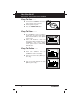
You Can Do It! EASY TO USE - EASY TO VIEW - EASY TO DEFINE Easy To Use . . . . ■ Connect the CanOBD2&1 Scan Tool to the vehicle’s test connector. ■ Turn the ignition key "On.” ■ Press the POWER/LINK button. Easy To View . . . . ■ The CanOBD2&1 Scan Tool retrieves stored codes, as well as Freeze Frame data and I/M Readiness status (OBD2 systems only). ■ Codes, I/M Readiness status and Freeze Frame data are displayed on the CanOBD2&1 Scan Tool’s display screen.
Safety Precautions SAFETY FIRST! SAFETY FIRST! To avoid personal injury, instrument damage and/or damage to your vehicle; do not use the CanOBD2&1 Scan Tool before reading this manual. This manual describes common test procedures used by experienced service technicians. Many test procedures require precautions to avoid accidents that can result in personal injury, and/or damage to your vehicle or test equipment.
Safety Precautions SAFETY FIRST! To prevent damage to the on-board computer when taking vehicle electrical measurements, always use a digital multimeter with at least 10 megOhms of impedance. Fuel and battery vapors are highly flammable. To prevent an explosion, keep all sparks, heated items and open flames away from the battery and fuel / fuel vapors. DO NOT SMOKE NEAR THE VEHICLE DURING TESTING. Don't wear loose clothing or jewelry when working on an engine.
About the CanOBD2&1 Scan Tool BATTERY INSTALL / REPLACEMENT / ADJUSTMENTS/SETTINGS & DTC LIBRARY BATTERY INSTALLATION / REPLACEMENT Replace batteries when the battery symbol is visible on display and/or the 3 LEDS are all lit and no other data is visible on screen. 1. Locate the battery cover on the back of the CanOBD2&1 Scan Tool. 2. Slide the battery cover off (use your fingers). 3. Replace batteries with three AA-size batteries (for longer life, use Alkaline-type batteries). 4.
About the CanOBD2&1 Scan Tool ADJUSTMENTS/SETTINGS AND DTC LIBRARY Adjustments and settings can be made only when the CanOBD2&1 Scan Tool is NOT connected to a vehicle. To enter the MENU Mode: 1. With the CanOBD2&1 Scan Tool OFF, press and hold the UP button, then press and release the POWER/LINK button. ■ The Setup Menu displays. 2. Release the UP button. DO NOT release the UP visible on the display. button until the Setup Menu is 3.
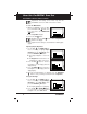
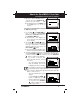
About the CanOBD2&1 Scan Tool ADJUSTMENTS/SETTINGS AND DTC LIBRARY 3. When the desired backlight mode is selected, press the ENTER/LD button to save your changes. ■ The display returns to the MENU, and the backlight turns “on” or “off” as selected. Searching for a DTC Definition Using the DTC Library (applicable to OBD2 systems only) 1. Use the UP and DOWN buttons, as necessary, to highlight DTC Library in the Setup Menu, then press the ENTER/LD button. ■ The Enter DTC screen displays.
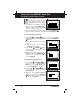
About the CanOBD2&1 Scan Tool ADJUSTMENTS/SETTINGS AND DTC LIBRARY If a definition for the DTC you entered is not available, an advisory message shows on the CanOBD2&1 Scan Tool’s display. 4. If you wish to view definitions for additional DTCs, press the ENTER/LD button to return to the DTC Library screen, and repeat steps 2 and 3. 5. When all desired DTCs have been viewed, press the ERASE button to exit the DTC Library and return to the Setup Menu. Selecting the Display Language 1.
About the CanOBD2&1 Scan Tool ADJUSTMENTS/SETTINGS AND DTC LIBRARY Exiting the MENU Mode 1. Use the UP and DOWN buttons, as necessary, to highlight Menu Exit in the Setup Menu, then press the ENTER/LD button. ■ If diagnostic data IS currently stored in the CanOBD2&1 Scan Tool’s memory, the stored data is shown on the display. ■ If diagnostic data IS NOT currently stored in the CanOBD2&1 Scan Tool’s memory, the “Linking Instructions” screen is shown on the display.
CanOBD2&1 Scan Tool Controls CONTROLS AND INDICATORS CONTROLS AND INDICATORS 11 10 7 6 8 9 1 3 2 4 5 16 12 13 14 15 Figure 1. Controls and Indicators See Figure 1 for the locations of items 1 through 16, below. 1. ERASE button - Erases Diagnostic Trouble Codes (DTCs), and “Freeze Frame” data from your vehicle’s computer, and resets Monitor status. (“Freeze Frame” data and Monitor status are applicable to OBD2 systems only.) 2.
CanOBD2&1 Scan Tool Controls CONTROLS AND INDICATORS 4. ENTER/LIVE DATA button - When in MENU mode, confirms the selected option or value. When linked to a vehicle, places the CanOBD2&1 Scan Tool in "Live Data" mode. 5. DOWN button - When in MENU mode, scrolls DOWN through the menu and submenu selection options. When retrieving and viewing DTCs, scrolls down through the current display screen to display any additional data. 6.
CanOBD2&1 Scan Tool Controls DISPLAY FUNCTIONS DISPLAY FUNCTIONS 2 1 11 12 13 3 4 5 6 15 16 7 14 8 10 9 Figure 2. Display Functions See Figure 2 for the locations of items 1 through 16, below. 1. I/M MONITOR STATUS field - Identifies the I/M Monitor status area. (This function is applicable to OBD2 systems only.) 2. Monitor icons - Indicate which Monitors are supported by the vehicle under test, and whether or not the associated Monitor has run its diagnostic testing (Monitor status).
CanOBD2&1 Scan Tool Controls DISPLAY FUNCTIONS 6. CanOBD2&1 Scan Tool Internal Battery icon - When visible, indicates the CanOBD2&1 Scan Tool batteries are “low” and should be replaced. If the batteries are not replaced when the battery symbol is "on", all 3 LEDs will light up as a last resort indicator to warn you that the batteries need replacement. No data will be displayed on screen when all 3 LEDs are lit. 7. DTC Display Area - Displays the Diagnostic Trouble Code (DTC) number.
CanOBD2&1 Scan Tool Controls VIEWING DTCs IN THE CANOBD2&1 SCAN TOOL’S MEMORY VIEWING DTCs IN THE CANOBD2&1 SCAN TOOL’S MEMORY To view DTC’s and other diagnostic data stored in the CanOBD2&1 Scan Tool’s memory, do the following: 1. With no DLC cable connected to the CanOBD2&1 Scan Tool, press the POWER/LINK “on”. ■ button to turn the CanOBD2&1 Scan Tool The “To Retrieve DTCs” screen shows on the CanOBD2&1 Scan Tool’s display. Press the button for instructions to view DTC’s in memory. 2.
Preparation for Testing PRELIMINARY VEHICLE DIAGNOSIS WORKSHEET PRELIMINARY VEHICLE DIAGNOSIS WORKSHEET The purpose of this form is to help you gather preliminary information on your vehicle before you retrieve codes. By having a complete account of your vehicle's current problem(s), you will be able to systematically pinpoint the problem(s) by comparing your answers to the fault codes you retrieve.
Preparation for Testing PRELIMINARY VEHICLE DIAGNOSIS WORKSHEET WHEN DID YOU FIRST NOTICE THE PROBLEM: ❑ ❑ ❑ ❑ Just Started Started Last Week Started Last Month Other: LIST ANY REPAIRS DONE IN THE PAST SIX MONTHS: PROBLEMS STARTING ❑ No symptoms ❑ Will not crank ❑ Cranks, but will not start ❑ Starts, but takes a long time ENGINE QUITS OR STALLS ❑ No symptoms ❑ Right after starting ❑ When shifting into gear ❑ During steady-speed driving ❑ ❑ ❑ ❑ IDLING CONDITIONS ❑ No symptoms ❑ Is too slow at all tim
Preparation for Testing PRELIMINARY VEHICLE DIAGNOSIS WORKSHEET AUTOMATIC TRANSMISSION PROBLEMS (if applicable) ❑ No symptoms ❑ Vehicle does not move when in gear ❑ Shifts too early or too late ❑ Jerks or bucks ❑ Changes gear incorrectly PROBLEM OCCURS ❑ Morning ❑ Afternoon ❑ Anytime ENGINE TEMPERATURE WHEN PROBLEM OCCURS ❑ Cold ❑ Warm ❑ Hot DRIVING CONDITIONS WHEN PROBLEM OCCURS ❑ Short - less than 2 miles ❑ With headlights on ❑ 2 - 10 miles ❑ During acceleration ❑ Long - more than 10 miles ❑ Mostly
Preparation for Testing BEFORE YOU BEGIN BEFORE YOU BEGIN The CanOBD2&1 Scan Tool aids in monitoring electronicand emissions-related faults in your vehicle and retrieving fault codes related to malfunctions in these systems. Mechanical problems such as low oil level or damaged hoses, wiring or electrical connectors can cause poor engine performance and may also cause a fault code to set. Fix any known mechanical problems before performing any test.
Preparation for Testing VEHICLE SERVICE MANUALS VEHICLE SERVICE MANUALS Always refer to the manufacturer’s service manual for your vehicle before performing any test or repair procedures. Contact your local car dealership, auto parts store or bookstore for availability of these manuals.
General Code Retrieval Procedures OBD1 SYSTEMS / OBD2 SYSTEMS Procedures for Retrieving Diagnostic Trouble Codes from OBD1 systems are vehicle manufacturer specific. Each manufacturer uses their own procedure. Procedures for retrieving Diagnostic Trouble Codes from OBD2 systems are generic, and apply to all vehicles equipped with OBD2 systems. From the following list, select the procedure that applies to your vehicle’s OBD system, and proceed to appropriate section for detailed code retrieval procedures.
OBD2 Systems VEHICLES COVERED VEHICLES COVERED The CanOBD2&1 Scan Tool is designed to work on all OBD 2 compliant vehicles. All 1996 and newer vehicles (cars and light trucks) sold in the United States are OBD 2 compliant. Federal law requires that all 1996 and newer cars and light trucks sold in the United States must be OBD 2 compliant; this includes all Domestic, Asian and European vehicles. Some 1994 and 1995 vehicles are OBD 2 compliant.
OBD2 Systems DIAGNOSTIC TROUBLE CODES (DTCs) On some Asian and European vehicles the DLC is located behind the “ashtray” (the ashtray must be removed to access it) or on the far left corner of the dash. If the DLC cannot be located, consult the vehicle’s service manual for the location. DIAGNOSTIC TROUBLE CODES (DTCs) Diagnostic Trouble Codes (DTCs) are meant to guide you to the proper service procedure in the vehicle’s service manual.
OBD2 Systems DIAGNOSTIC TROUBLE CODES (DTCs) OBD 2 DTC EXAMPLE P0201 - Injector Circuit Malfunction, Cylinder 1 B C P U - Body Chassis Powertrain Network 0 1 2 3 - Generic Manufacturer Specific Generic Includes both Generic and Manufacturer Specific Codes P0201 Identifies the system where the problem is located: 1 - Fuel and Air Metering 2 - Fuel and Air Metering (injector circuit malfunction only) 3 - Ignition System or Misfire 4 - Auxiliary Emission Control System 5 - Vehicle Speed Control and Idl
OBD2 Systems CODE RETRIEVAL PROCEDURE CODE RETRIEVAL PROCEDURE Retrieving and using Diagnostic Trouble Codes (DTCs) for troubleshooting vehicle operation is only one part of an overall diagnostic strategy. Never replace a part based only on the DTC definition. Each DTC has a set of testing procedures, instructions and flow charts that must be followed to confirm the location of the problem. This information is found in the vehicle's service manual.
OBD2 Systems CODE RETRIEVAL PROCEDURE ■ If the unit does not power on automatically when connected to the vehicle’s DLC connector, it usually indicates there is no power present at the vehicle’s DLC connector. Check your fuse panel and replace any burned-out fuses. ■ If replacing the fuse(s) does not correct the problem, consult your vehicle’s repair manual to identify the proper computer (PCM) fuse/ circuit, and perform any necessary repairs before proceeding. 5. Turn the ignition on.
OBD2 Systems CODE RETRIEVAL PROCEDURE ■ The CanOBD2&1 Scan Tool will automatically re-link to the vehicle’s computer every 30 seconds to refresh the data being retrieved. When data is being refreshed, the message “One moment Auto – link in progress” is shown on the display. This action repeats as long as the CanOBD2&1 Scan Tool is communicating with the vehicle’s computer. ■ The CanOBD2&1 Scan Tool will display a code only if codes are present in the vehicle’s computer memory.
OBD2 Systems CODE RETRIEVAL PROCEDURE In the case of long code definitions, or when viewing Freeze Frame data, a small arrow is shown in the upper/lower right-hand corner of the code display area to indicate the presence of additional information. Use the and buttons, as necessary, to view the additional information. 9. Read and interpret Diagnostic Trouble Codes/system condition using the display and the green, yellow and red LEDs.
OBD2 Systems CODE RETRIEVAL PROCEDURE ■ Red LED – Indicates there is a problem with one or more of the vehicle’s systems. The red LED is also used to indicate that DTC(s) are present (displayed on the CanOBD2&1 Scan Tool’s screen). In this case, the Malfunction Indicator (Check Engine) lamp on the vehicle’s instrument panel will be illuminated. ■ DTC’s that start with “P0”, “P2” and some “P3” are considered Generic (Universal). All Generic DTC definitions are the same on all OBD2 equipped vehicles.
OBD2 Systems CODE RETRIEVAL PROCEDURE 10. If more than one code was retrieved press the DTC SCROLL button, as necessary, to display additional codes one at a time. ■ Each time the DTC SCROLL button is pressed and released, the CanOBD2&1 Scan Tool will scroll and display the next DTC in sequence until all DTCs in its memory have displayed. ■ Freeze Frame Data (if available) will display after DTC #1.
OBD2 Systems ERASING DIAGNOSTIC TROUBLE CODES (DTCs) ■ To prolong battery life, the CanOBD2&1 Scan Tool automatically shuts “Off” approximately three minutes after it is disconnected from the vehicle. The DTCs retrieved, Monitor Status and Freeze Frame data (if any) will remain in the CanOBD2&1 Scan Tool’s memory, and may be viewed at any time by turning the unit “On”.
OBD2 Systems I/M READINESS TESTING 3. Press and release the ERASE button. A confirmation message shows on the LCD display. - If you are sure you want to proceed press the ERASE button again to erase DTCs from the vehicle’s computer. - If you do not want to continue with the erase process, press the POWER/LINK button to exit the erase mode. 4. If you chose to erase DTCs, a progress screen displays while the erase function is in progress.
OBD2 Systems I/M READINESS TESTING Emissions tests vary depending on the geographic or regional area in which the vehicle is registered. If the vehicle is registered in a highly urbanized area, the I/M 240 is probably the type of test required. If the vehicle is registered in a rural area, the stricter “dynamometer type” test may not be required.
OBD2 Systems I/M READINESS TESTING ■ If a Monitor was able to meet all the conditions required to enable it to perform the self-diagnosis and testing of its assigned engine system, it means the monitor "HAS RUN.” ■ If a Monitor has not yet met all the conditions required for it to perform the self-diagnosis and testing of its assigned engine system; it means the Monitor "HAS NOT RUN.” The Monitor Run/Not Run status does not show whether or not a problem exists in a system.
OBD2 Systems I/M READINESS TESTING Monitors with a "Has Run" status indicate that all the required conditions they needed to perform diagnosis and testing of their assigned engine area (system) have been met, and all diagnostic testing has completed successfully. Monitors with a "Has Not Run" status have not yet met the conditions they need to perform diagnosis and testing of their assigned engine area (system), and have not been able to perform diagnostic testing on that system.
OBD2 Systems I/M READINESS TESTING - Some areas require that all Monitors indicate a "Has Run" status before they allow an Emissions Test (Smog Check) to be performed. Other areas only require that some, but not all, Monitors have run their self-diagnostic testing before an Emissions Test (Smog Check) may be performed. From the code retrieval procedure, determine the status of each Monitor (a solid Monitor icon shows Monitor "Has Run" status, a flashing Monitor icon indicates "Has Not Run" status).
OBD2 Systems I/M READINESS TESTING ■ See page 30 for procedures to erase DTCs from the vehicle's onboard computer. ■ Write the codes down on a piece of paper for reference before erasing. 3. After the erase procedure is performed, most of the Monitor icons on the CanOBD2&1 Scan Tool’s display will be flashing.
OBD2 Live Data Mode VIEWING LIVE DATA The CanOBD2&1 Scan Tool is a special diagnostic tool that communicates with the vehicle's computer. The CanOBD2&1 Scan Tool lets you view and/or "capture" (record) "real-time" Live Data. This information includes values (volts, rpm, temperature, speed etc.) and system status information (open loop, closed loop, fuel system status, etc.) generated by the various vehicle sensors, switches and actuators.
OBD2 Live Data Mode CUSTOMIZING LIVE DATA (PIDs) ■ If communication with the vehicle is lost while viewing Live Data, a Communication Lost" message shows on the CanOBD2&1 Scan Tool's display. 5. If you experience vehicle problems, view and/or compare the Live Data (PID) information displayed on the CanOBD2&1 Scan Tool to specifications in the vehicle's repair manual. If desired, you can "customize" the Live Data display to show only those PIDs you are interested in viewing.
OBD2 Live Data Mode RECORDING (CAPTURING) LIVE DATA ■ The "Custom Live Data" menu displays, with the first PID in the menu highlighted. 4. Use the UP and DOWN buttons to scroll through the available PIDs. When the PID you wish to display is highlighted, press the ENTER/LD button to select it (a "checkmark" will show in the checkbox to the right of the PID to confirm your selection). Repeat the procedure until only the PIDs you want to display have all been selected.
OBD2 Live Data Mode RECORDING (CAPTURING) LIVE DATA 1. With the CanOBD2&1 Scan Tool in "Live Data" mode (see Viewing Live Data on page 37 for details), press and hold the ENTER/LD button until the "Mode Selection Menu" appears. 2. Use the UP and DOWN buttons, as necessary, to highlight Live Data Menu, then press the ENTER/LD button. ■ The "Live Data Menu" displays. 3. Use the UP and DOWN buttons, as necessary, to highlight Record Live Data, then press the ENTER/LD button.
OBD2 Live Data Mode RECORDING (CAPTURING) LIVE DATA ■ A "One moment please. . ." message shows on the display. When the CanOBD2&1 Scan Tool is ready to record Live Data, the "Record Live Data" screen displays. 7. Put the engine in the operating condition that causes the DTC to set. ■ If necessary, drive the vehicle until you reach the vehicle speed at which the problem occurs. 8.
OBD2 Live Data Mode RECORDING (CAPTURING) LIVE DATA 1. With the CanOBD2&1 Scan Tool in "Live Data" mode (see Viewing Live Data on page 37 for details), press and hold the ENTER/LD button until the "Mode Selection Menu" appears. 2. Use the UP and DOWN buttons, as necessary, to highlight Live Data Menu, then press the ENTER/LD button. ■ The "Live Data Menu" displays. 3. Use the UP and DOWN buttons, as necessary, to highlight Record Live Data, then press the ENTER/LD button.
OBD2 Live Data Mode RECORDING (CAPTURING) LIVE DATA ■ A "One moment please. . ." message shows on the display. When the CanOBD2&1 Scan Tool is ready to record Live Data, the "Record Live Data" screen displays. 7. Put the engine in the operating condition where the problem manifests itself. ■ If necessary, drive the vehicle until you reach the vehicle speed at which the problem occurs. 8. When the problem occurs, press and release the ENTER/LD button.
OBD2 Live Data Mode LIVE DATA PLAYBACK SCROLL or the ENTER/LD buttons. The CanOBD2&1 Scan Tool will stay linked to the vehicle’s computer during this process. However, if the DTC SCROLL button is pressed twice the DTC screen will be advanced to the next DTC screen and the CanOBD2&1 Scan Tool will be taken out of link. LIVE DATA PLAYBACK Once Live Data has been recorded, it is saved in the CanOBD2&1 Scan Tool's memory.
OBD2 Live Data Mode LIVE DATA PLAYBACK ■ Use the UP and DOWN buttons, as necessary, to highlight OBD2 Vehicle, then press the ENTER/LD button. The display shows the first DTC stored in the CanOBD2&1 Scan Tool’s memory. ■ Press the ENTER/LD button to place the CanOBD2&1 Scan Tool in "Live Data Playback" mode. 3. The display shows the recorded Live Data, beginning with the "trigger" frame.
Generic (Global) OBD2 PID List ■ If the Code Reader is connected to a vehicle, use the DOWN button to scroll to the end of the PID list, highlight Exit Playback, then press the ENTER/LD button. ■ If the Code Reader is not connected to a vehicle, press the DTC SCROLL button. The following is a list of Generic (Global) PIDs and their descriptions. Tool Display Unit Value PID Description ACC Pedal D % XXX.X Accelerator Pedal Position D ACC Pedal E % XXX.
Generic (Global) OBD2 PID List Tool Display Unit Value PID Description EQ Ratio 11 - X.XXX EQ Ratio 12 - X.XXX EQ Ratio 13 - X.XXX EQ Ratio 14 - X.XXX EQ Ratio 21 - X.XXX EQ Ratio 22 - X.XXX EQ Ratio 23 - X.XXX EQ Ratio 24 - X.
Generic (Global) OBD2 PID List Tool Display Unit LTFT B3 LTFT B4 MAF % % g/s ; lb/min MAP kPa / PSI MIL On Time hrs, min Monitor Status - Long Term Fuel Trim-Bank 3 Long Term Fuel Trim-Bank 4 Air Flow Rate from Mass Air Flow Sensor Intake Manifold Absolute Pressure Engine Run Time while MIL ON Monitor Status this Driving Cycle S1 S1 mA S1 V S2 S2 mA S2 V S3 S3 mA S3 V S4 S4 mA V mA V V mA V V mA V V mA O2S B1 S4 V O2S B2 S1 O2S B2 S1 mA O2S B2 S1 V O2S B2 S2 O2S B2 S2 mA O2S B2 S2 V O2S B2 S3 O2S B2
Generic (Global) OBD2 PID List Tool Display Unit Value O2S Location O2S Location O2S Location O2S Location O2S Location O2S Location O2S Location O2S Location O2S Location O2S Location O2S Location OBD Support OBD Support OBD Support - Oxygen Sensor, Bank 2, Sensor 1 Oxygen Sensor, Bank 2, Sensor 3 Oxygen Sensor, Bank 2, Sensor 4 Oxygen Sensor, Bank 1, Sensor 1 Oxygen Sensor, Bank 1, Sensor 2 Oxygen Sensor, Bank 2, Sensor 1 Oxygen Sensor, Bank 2, Sensor 2 Oxygen Sensor, Bank 3, Sensor 1 Oxygen Sensor,
Generic (Global) OBD2 PID List Tool Display Value PID Description STFT B1 S4 % XXX.X Bank 1 - Sensor 4 STFT B2 % XXX.X Short Term Fuel Trim-Bank 2 STFT B2 S1 % XXX.X Bank 2 - Sensor 1 STFT B2 S2 % XXX.X Bank 2 - Sensor 2 STFT B2 S3 % XXX.X Bank 2 - Sensor 3 STFT B2 S4 % XXX.X Bank 2 - Sensor 4 STFT B3 % XXX.X Short Term Fuel Trim-Bank 3 STFT B4 % XXX.
Additional OBD2 Tests O2 SENSOR TEST In addition to retrieving Diagnostic Trouble Code (DTC) and viewing Live Data, you can use the CanOBD2&1 Scan Tool to perform additional diagnostic tests, and to view diagnostic and vehicle information stored in your vehicle's on-board computer. Additional tests are accessed through the "Mode Selection Menu.
Additional OBD2 Tests O2 SENSOR TEST ■ X or XX - These characters identify the location of the O2 sensor in relation to a cylinder bank. An O2 sensor for cylinder bank 1 is identified by the designation “1” or "B1"; a sensor for cylinder bank 2 is identified as “2” or "B2." ”Bank One” indicates the side of the engine where cylinder number one is located (V-type engines). Bank Two is opposite of Bank One.
Additional OBD2 Tests NON-CONTINUOUS TEST 5. When you have finished viewing the retrieved test data, scroll to the end of the display to select Exit, then press the ENTER/LD button to return to the "Select Test" screen. NON-CONTINUOUS TEST The Non-Continuous Test function retrieves and displays test results for emission-related powertrain components and systems that are not continuously monitored. The tests available are determined by the vehicle manufacturer.
Additional OBD2 Tests SYSTEM TEST ■ Test ID number ■ Module ID number ■ Component ID number ■ Min or Max test limit Only one test limit, either Min or Max, is shown for any given test. ■ Test Value and status Status is calculated by the CanOBD2&1 Scan Tool by comparing the Test Value against the displayed test limit (either Min or Max). Status is shown as either Low, High or OK. 5.
Additional OBD2 Tests VEHICLE ID Some vehicle manufacturers do not allow CanOBD2&1 Scan Tools or other external devices to control vehicle systems. If the EVAP Leak Test is not supported by the vehicle under test, an advisory message shows on the CanOBD2&1 Scan Tool's display. Press the ENTER/LD button to return to the System Test menu. 4. When the EVAP leak test has been initiated by the vehicle's on-board computer, a confirmation message shows on the CanOBD2&1 Scan Tool's display.
Additional OBD2 Tests VEHICLE ID If the Vehicle ID function is not supported by the vehicle under test, an advisory message shows on the CanOBD2&1 Scan Tool's display. Press the ENTER/LD button to return to the Mode Selection menu. 2. Use the UP and DOWN buttons, as necessary, to highlight Vehicle ID, then press the ENTER/LD button. 3. A "One moment please..." message displays while the requested information is retrieved from the vehicle's computer.
Additional OBD2 Tests VEHICLE ID 2. Use the UP and DOWN buttons, as necessary, to highlight Available Modules, then press the ENTER/LD button. 3. A "One moment please..." message displays while the requested information is retrieved from the vehicle's computer. 4. When the retrieval process is completed, a complete list of modules supported by the vehicle under test is shown on the CanOBD2&1 Scan Tool's display. Use the UP and DOWN buttons, as necessary, to view the entire list. 5.
Chrysler/Jeep OBD1 Systems CHRYSLER/JEEP OBD1 SYSTEMS CHRYSLER/JEEP OBD1 SYSTEMS Chrysler Motors On-Board Computer Systems Chrysler Motors introduced its first electronic fuel injected vehicle in late 1983. The on-board computer management systems used on Chrysler vehicles have evolved over the years, and their names have changed accordingly. 1983-87: The on-board computer used in these vehicles is a splitsystem, composed of two separate units: the Logic Module and the Power Module.
Chrysler/Jeep OBD1 Systems VEHICLES COVERED / PANEL INDICATOR LIGHTS / DLC VEHICLES COVERED This section covers Chrysler fuel injected vehicles from 1983-1995. Model Year Type Model Passenger Cars 1983-1995 Chrysler, Dodge and Plymouth Fuel Injected Models Only (Excluding Lasor/Talon 1.8L, 2.
Chrysler/Jeep OBD1 Systems CODE RETRIEVAL PROCEDURE CODE RETRIEVAL PROCEDURE Retrieving and using Diagnostic Trouble Codes (DTCs) for troubleshooting vehicle operation is only one part of an overall diagnostic strategy. Never replace a part based only on the DTC definition. Each DTC has a set of testing procedures, instructions and flow charts that must be followed to confirm the location of the problem. This information is found in the vehicle’s service manual.
Chrysler/Jeep OBD1 Systems CODE RETRIEVAL PROCEDURE ■ To retrieve DTCs from the vehicle selection currently in the CanOBD2&1 Scan Tool’s memory: - From the “Current Selection/ Select New Vehicle” screen, highlight Current Selection and press the ENTER/LD button. - Proceed to step 5 to continue. ■ To retrieve DTCs from a new vehicle: - From the “Current Selection/ Select New Vehicle” screen, highlight Select New Vehicle and press the ENTER/LD button; the “Select Vehicle Year” menu displays.
Chrysler/Jeep OBD1 Systems CODE RETRIEVAL PROCEDURE ■ If the CanOBD2&1 Scan Tool fails to link to the vehicle’s computer, a “Vehicle is not responding” message shows on the CanOBD2&1 Scan Tool’s display. Do the following: - Verify the ignition is ON. - Check the cable connections at the CanOBD2&1 Scan Tool and at the vehicle’s DLC. - Turn the ignition OFF, wait 10-12 seconds, then turn back ON to reset the computer. - Press the ENTER/LD button and repeat steps 4 through 6 as necessary. 7.
Chrysler/Jeep OBD1 Systems CODE RETRIEVAL PROCEDURE 11. Follow the testing and repair procedures outlined in the vehicle's service repair manual to correct "hard" DTCs. Codes should be addressed and eliminated in the order they were received, erasing (see Erasing DTC's on page 102) and retesting after each repair is made to be sure the fault was eliminated. The green, yellow and red LEDs are used (with the LCD display) as visual aids to make it easier to determine engine system conditions.
Ford OBD1 Systems FORD COMPUTER SYSTEM OVERVIEW - VEHICLES COVERED FORD COMPUTER SYSTEM OVERVIEW The CanOBD2&1 Scan Tool is compatible only with EEC-IV Computer Control systems. IMPORTANT: When the computer is in Self-Test mode (is testing the sensors or actuators for proper operation), it relies on voltage signals that is sends to and / or receives from the sensors or actuators to determine whether or not these components are operating properly.
Ford OBD1 Systems VEHICLES COVERED - CARS 8th VIN Digit** Fuel Systems (Carburetor Model) 5.0L V-8 F, M CFI, SEFI 1.9L I-4 J, 9 EFI, CFI, SFI 2.0L I-4 A SEFI Probe (1993 manual transmission only) 2.
Ford OBD1 Systems VEHICLES COVERED - TRUCKS Engine 8th VIN Digit** Fuel Systems (Carburetor Model) 4.6L V8 DOHC V SFI Mark VIII 5.0L V-8 HO T SFI Mustang 5.0L V-8 SHP D Application/Special Notes Computer System 1995 (Cont) EEC-IV NOTES * Carburetor Model. Carburetor model numbers are usually stamped on top of the carburetor, or on a metal tab attached to the carburetor. Consult your vehicle’s repair manual for proper identification. **VIN Number.
Ford OBD1 Systems VEHICLES COVERED - TRUCKS/VANS 8th VIN Digit** Fuel Systems (Carburetor Model) 3.0L V-6 U EFI, SEFI, SFI 4.0L V-6 X EFI, MFI 4.9L I-6 5.0L V-8 5.8L V-8 Y, H N H, R EFI, MFI, SFI EFI, MFI, SFI EFI, MFI, SFI Bronco, E and F Series Trucks/ Vans (8500 lb. GVW or less only) 7.3L V-8 7.3L V-8 7.5L V-8 M K G Diesel Turbo Diesel EFI, MFI E and F Series Trucks/Vans (Excludes 1994 diesel models) 3.0L V-6 U SFI 4.0L V-6 X SFI 4.
Ford OBD1 Systems TEST CONNECTORS - CONNECTING THE CANOBD2&1 SCAN TOOL TEST CONNECTORS Ford vehicles are equipped with special test connectors that make it possible to connect specialized testing equipment that communicates with the vehicle's onboard computer. Ford's vehicle test connectors are usually dark in color (BLACK or GREY). Sometimes they have a plastic cover over them or are labeled EEC Test.
Ford OBD1 Systems DIAGNOSTIC TROUBLE CODES / CODE RETRIEVAL PROCEDURES - OVERVIEW DIAGNOSTIC TROUBLE CODES (DTCs) Diagnostic Trouble Codes, or Fault Codes, can be used to identify engine systems or components that are malfunctioning.
Ford OBD1 Systems CODE RETRIEVAL PROCEDURES - KOEO TEST As described previously, some tests are designed to detect problems only when the vehicle is in normal operation. Some tests are designed to activate components and detect problems only with the Key On and Engine Off. Other tests are designed to activate components and test their operation only with the Key On and Engine Running. Do not take short cuts.
Ford OBD1 Systems CODE RETRIEVAL PROCEDURES - KOEO TEST 5. Turn ignition key OFF and wait for the on-screen prompt. If you wish to exit the KOEO test at this time, press the ENTER/LD to return to the Ford EEC-IV System menu. button 6. When prompted by the CanOBD2&1 Scan Tool, turn the ignition ON. DO NOT start the engine. If your vehicle is equipped with one of the following engine types, perform the added procedures described below: ■ For 4.
Ford OBD1 Systems CODE RETRIEVAL PROCEDURES - KOEO TEST - Press ENTER/LD button to continue. 9. If the CanOBD2&1 Scan Tool was able to link to the vehicle successfully a "Code retrieval was successful..." message shows temporarily on the CanOBD2&1 Scan Tool's display followed by any retrieved DTCs. ■ The CanOBD2&1 Scan Tool will display a code only if codes are present in the vehicle's computer memory.
Ford OBD1 Systems CODE RETRIEVAL PROCEDURES - ENGINE TIMING CHECK IMPORTANT: DO NOT service "Continuous Memory" codes at this time. Before "Continuous Memory" codes can be serviced, both the KOEO and the KOER Self-Tests must pass (a PASS code 11 or 111 is obtained). After both of these tests have passed, erase the vehicle's computer memory (see Erasing DTCs on page 102), take the vehicle for a short drive, then repeat the KOEO Self-Test.
Ford OBD1 Systems CODE RETRIEVAL PROCEDURES - ENGINE TIMING CHECK ■ A timing light is required to perform this test. ■ The vehicle must pass the KOEO Test (page 70) before performing this test. 1. Locate the vehicle's Data Link Connector (DLC). See Data Link Connector on page 68 for connector location. Some DLCs have a plastic cover that must be removed before connecting the CanOBD2&1 Scan Tool's cable connector. 2.
Ford OBD1 Systems CODE RETRIEVAL PROCEDURES - KOER TEST 7. When prompted by the CanOBD2&1 Scan Tool, start the engine and press the ENTER/LD ■ button. A "One moment please preparation for test is in progress” message shows temporarily on the CanOBD2&1 Scan Tool's display, followed by the message "Perform Timing Check within two minutes." 8.
Ford OBD1 Systems CODE RETRIEVAL PROCEDURES - KOER TEST Key on Engine Running (KOER) Self-Test IMPORTANT: The KOEO Self-Test (page 70) must be performed first, and a "pass code" (code 11 or 111) must be obtained before performing the KOER Self-Test; otherwise, results of the KOER Self-Test may be invalid. Ignition timing and timing advance must be operating properly in order for the KOER Self-Test results to be considered valid. Perform an Engine Timing check (page 73) before performing the KOER Self-Test.
Ford OBD1 Systems CODE RETRIEVAL PROCEDURES - KOER TEST 6. When prompted by the CanOBD2&1 Scan Tool, start the engine and press the ENTER/LD button to continue. A "One moment please KOER test is in progress..." message shows temporarily on the CanOBD2&1 Scan Tool's display. 7. The CanOBD2&1 Scan Tool will retrieve and display the Cylinder Identification (ID) Code. The Cylinder ID Code identifies the number of cylinders of the vehicle that is under test.
Ford OBD1 Systems ADDITIONAL TESTS FOR EEC-IV SYSTEMS Most Ford EEC-IV vehicle computers up to 1991 use a twodigit code system. From 1991 to 1995 most use a three-digit code system. 11. If no problems are found during the KOER Self-Test, the computer sends a "PASS code" (code 11 or 111) to the CanOBD2&1 Scan Tool. Code 11 or 111 indicates that all the relays and actuators and their related circuits that were tested during the KOER Self-Test are OK, and no faults were found. 12.
Ford OBD1 Systems ADDITIONAL TESTS FOR EEC-IV SYSTEMS - CYLINDER BALANCE TEST Cylinder Balance Test (Vehicles equipped with Sequential Electronic Fuel Injected (SEFI) systems only) The Cylinder Balance Test assists in finding a weak or noncontributing cylinder. The computer shuts off fuel (cuts off power to injectors) to each cylinder, in sequence, and monitors for RPM changes (drop).
Ford OBD1 Systems ADDITIONAL TESTS FOR EEC-IV SYSTEMS - CYLINDER BALANCE TEST 3. From the Ford EEC-IV System menu, highlight Cylinder Balance Test, then press the ENTER/LD button. ■ An “application” advisory message shows on the CanOBD2&1 Scan Tool’s display. ■ If your vehicle IS equipped with the Sequential Fuel Injection, press the ENTER/LD ■ button to continue. If your vehicle IS NOT equipped with Sequential Fuel Injection, select Back, then press the ENTER/LD Cylinder Balance Test.
Ford OBD1 Systems ADDITIONAL TESTS FOR EEC-IV SYSTEMS -RELAY AND SOLENOID TEST Check your vehicle's fuel injection system and make sure that it is a Sequential Electronic Fuel Injection (SEFI) system. This test is applicable only to SEFI or SFI systems. 9. After the Cylinder Balance Test is completed, the test results are sent to the CanOBD2&1 Scan Tool. ■ The computer compares the power contribution that each cylinder makes to engine operation. 10.
Ford OBD1 Systems ADDITIONAL TESTS FOR EEC-IV SYSTEMS -RELAY AND SOLENOID TEST The fuel injectors and fuel pump are not energized during this test. Check your vehicle thoroughly before performing any test. See Before You Begin on page 18 for details. ALWAYS observe safety precautions whenever working on a vehicle. Read and follow Safety Precautions on page 3 before performing this test. 1. Locate the vehicle's Data Link Connector (DLC). See Data Link Connector (DLC) on page 68 for connector location.
Ford OBD1 Systems ADDITIONAL TESTS FOR EEC-IV SYSTEMS - RELAY AND SOLENOID TEST 7. Press the ENTER/LD button to continue. 8. A "One moment please test is in progress..." message shows on the CanOBD2&1 Scan Tool's display. As soon as the ignition is turned "on", the vehicle's computer enters the Self-Test mode. Clicking sounds will be heard coming from the engine. This is normal.
Ford OBD1 Systems ADDITIONAL TESTS FOR EEC-IV SYSTEMS -WIGGLE TEST 12. The procedure can be repeated as many times as desired by pressing and releasing the accelerator pedal to energize and de-energize the actuators. 13. Consult the vehicle's service repair manual for a list of actuators (solenoids and relays) controlled by the computer that apply to the vehicle under test, and which actuators should energize and deenergize when performing the Output State Check.
Ford OBD1 Systems ADDITIONAL TESTS FOR EEC-IV SYSTEMS -WIGGLE TEST 2. Connect the CanOBD2&1 Scan Tool cable (with the Ford Connector Cable Adaptor attached) to the CanOBD2&1 Scan Tool, then connect the adaptor to the vehicle's DLC. Press the POWER/LINK button to turn the CanOBD2&1 Scan Tool ON, then press the ENTER/LD ■ button to continue. The Ford EEC-IV System menu displays. Use the selections. and buttons, as necessary, to make menu 3.
Ford OBD1 Systems ADDITIONAL TESTS FOR EEC-IV SYSTEMS -WIGGLE TEST For KOER Wiggle Test: - Turn the engine OFF, wait 10 seconds, then turn back ON. Press the ENTER/LD button to continue. BE SURE to perform the added procedures in step 6, if appropriate for your vehicle, BEFORE turning the ignition ON. - Press ENTER/LD button to continue. 8. If the CanOBD2&1 Scan Tool was able to link to the vehicle successfully, a "Wiggle test is active..." message shows temporarily on the CanOBD2&1 Scan Tool’s display.
GM OBD1 Systems YOUR VEHICLE’S COMPUTER SYSTEM - VEHICLES COVERED YOUR VEHICLE'S COMPUTER SYSTEM Today's vehicles are equipped with computer self-testing abilities that can locate problems in your vehicle and store them as Diagnostic Trouble Codes (DTC's) in the vehicle's onboard computer. The CanOBD2&1 Scan Tool allows you access to the computer's memory and retrieves the DTC's.
GM OBD1 Systems ABOUT THE CANOBD2&1 SCAN TOOL - DLC - MIL Model Year 1995 Make Model Chevrolet Caprice 4.3 liter Saturn All models Trucks and Vans All one ton capacity or less with gas engines (EXCEPT S/T Series vehicles) In addition to the above list, the CanOBD2&1 Scan Tool IS ALSO COMPATIBLE with OBD1 GM models that are equipped with "Climate Control Computers". For 1994 and 1995 vehicles, only the models listed above are compatible with the CanOBD2&1 Scan Tool.
GM OBD1 Systems DTCs - CODE RETRIEVAL PROCEDURE DIAGNOSTIC TROUBLE CODES (DTC's) The service codes are also called "fault codes", "Diagnostic Trouble Codes" (DTC's) or "trouble codes". These codes can be used to identify systems or components that are malfunctioning.
GM OBD1 Systems CODE RETRIEVAL PROCEDURE Some DLCs have a plastic cover that must be removed before connecting the CanOBD2&1 Scan Tool's cable connector. 2. Connect the CanOBD2&1 Scan Tool cable (with the GM Connector Cable Adaptor attached) to the CanOBD2&1 Scan Tool, then connect the adaptor to the vehicle’s DLC. Press the POWER/LINK button to turn the CanOBD2&1 Scan Tool ON, then press the ENTER/LD to continue. button 3.
GM OBD1 Systems CODE RETRIEVAL PROCEDURE If the “Enter 4th VIN Digit” screen displays (not applicable to all vehicles), highlight the 4th digit of the vehicle’s VIN, then press the ENTER/LD button. - The “Current Selection/Select New Vehicle” screen displays for your confirmation. - If the information shown in the “Current Selection” field is correct, highlight Current Selection, turn ignition key ON (DO NOT start engine) and press the ENTER/LD button. Proceed to step 4 to continue.
GM OBD1 Systems CODE RETRIEVAL PROCEDURE In the case of long code definitions, a small arrow is shown in the upper.lower right-hand corner of the code display area to indicate the presence of additional information. Use the and buttons, as necessary, to view the additional information.
Toyota/Lexus OBD1 Systems ON-BOARD VEHICLE DIAGNOSTICS / VEHICLES COVERED ON-BOARD VEHICLE DIAGNOSTICS (OBD 1) • Beginning in 1988, California's Air Resources Board (CARB), and later, the Federal Government's Environmental Protection Agency (EPA), required vehicle manufacturers to include a self diagnostic program capable of identifying an emissions-related fault via the vehicles On-Board Computers (some manufacturers used OBD before it was required).
Toyota/Lexus OBD1 Systems VEHICLES COVERED Eng. Size Eng. Code DOHC/ SOHC Other DLC Type 1992 Celica Convertible 2.2L 5S-FE DOHC A/T 1 1992 Celica Coupe 1.6L 4A-FE DOHC 1992 Celica Coupe 2.2L 5S-FE DOHC 1993 Celica Coupe 1.6L 4A-FE DOHC 1 1995 Celica Coupe 1.8L 7A-FE DOHC 1 1992 Celica Liftback 2.0L 3S-GTE DOHC 1992 Celica Liftback 2.2L 5S-FE DOHC 1 1993 Corolla Sedan 1.6L 4A-FE DOHC 1 1993 Corolla Sedan 1.8L 7A-FE DOHC 1 1994 Corolla Sedan 1.
Toyota/Lexus OBD1 Systems VEHICLES COVERED Year Model Eng. Size Eng. Code DOHC/ SOHC 3VZ-FE DOHC Other DLC Type Turbo 2 1993 Camry 3.0L 1993 Supra 3.0L 1993 Supra 3.0L 2JZ-GE DOHC 1994 Camry 3.0L 3VZ-FE DOHC 1994 Supra 3.0L 1994 Supra 3.0L 1995 Supra 3.0L 1995 Supra 3.0L 2JZ-GE DOHC 2 1992 SC-300 3.0L 2JZ-GE DOHC 2 1990 ES-250 2.5L 2VZ-FE DOHC 2 1991 ES-250 2.5L 2VZ-FE DOHC 2 1992 ES-300 3.0L 3VZ-FE DOHC 2 1992 SC-400 4.
Toyota/Lexus OBD1 Systems DATA LINK CONNECTOR (DLC) / MIL DATA LINK CONNECTOR (DLC) Toyota vehicles are equipped with special Test Connectors that make it possible to connect specialized testing equipment that communicates with the vehicle's onboard computer. The CanOBD2&1 Scan Tool is designed for use with two types of Toyota DLC connectors; DLC Number 1 and DLC Number 2, as described below. The CanOBD2&1 Scan Tool's Toyota Connector Cable Adaptor is designed to match the vehicle's DLC.
Toyota/Lexus OBD1 Systems DIAGNOSTIC TROUBLE CODES / CODE RETRIEVAL PROCEDURE If your instrument panel indicator lights do not come on when you turn on the ignition, please refer to your vehicle's service manual. You may have problems in the car's circuitry. It is recommended that you fix these problems before retrieving DTCs from your vehicle’s computer. DIAGNOSTIC TROUBLE CODES Diagnostic Trouble Codes, or Fault Codes, can be used to identify engine systems or components that are malfunctioning.
Toyota/Lexus OBD1 Systems CODE RETRIEVAL PROCEDURE Check your vehicle thoroughly before performing any test. See Before You Begin on page 18 for details. ALWAYS observe safety precautions whenever working on a vehicle. See Safety Precautions on page 3 for more information. 1. Locate the vehicle's Data Link Connector (DLC). See Data Link Connector (DLC) on page 96 for connection location. Some DLCs have a plastic cover that must be removed before connecting the CanOBD2&1 Scan Tool's cable connector. 2.
Toyota/Lexus OBD1 Systems CODE RETRIEVAL PROCEDURE 7. If the CanOBD2&1 Scan Tool was able to link to the vehicle successfully a "Code retrieval was successful..." message shows temporarily on the CanOBD2&1 Scan Tool’s display followed by any retrieved DTCs. ■ The CanOBD2&1 Scan Tool will display a code only if codes are present in the vehicle's computer memory. If no codes are present, a "No DTC' are presently stored in the vehicle's computer" message is displayed. 8.
Servicing DTCs SERVICING DTCs - OBD I Retrieving and using Diagnostic Trouble Codes (DTCs) for troubleshooting vehicle operation is only one part of an overall diagnostic strategy. Never replace a part based only on the DTC definition. Each DTC has a set of testing procedures, instructions and flow charts that must be followed to confirm the location of the problem. This information is found in the vehicle's service manual. Always refer to the vehicle's service manual for detailed testing instructions. 1.
Servicing DTCs ■ HISTORY DTC - On some vehicles, the computer will keep a record or history of DTCs that relate to problems that happened in the past but are no longer present. These DTCs will not command the MIL or Check Engine light "On", but the yellow LED will be illuminated. 4. Red LED - Indicates there is a problem with one or more of the vehicle's systems. The red LED is also used to indicate that DTC(s) are present (displayed on the CanOBD2&1 Scan Tool's screen).
Erasing DTCs ERASING DTCs (OBD I SYSTEMS) When the CanOBD2&1 Scan Tool's ERASE function is used to erase DTCs from the vehicle's on-board computer, manufacturer specific data (where applicable) is also erased. If you plan to take the vehicle to a service center for repair, DO NOT erase the codes from the vehicle's computer. If the codes are erased, valuable information that might help the technician troubleshoot the problem will also be erased. Erase DTC’s from the computer’s memory as follows: 1.
Erasing DTCs ■ If the erase was not successful, an advisory message shows on the CanOBD2&1 Scan Tool’s display. Verify that the CanOBD2&1 Scan Tool is properly connected to the vehicle's DLC and that the ignition is ON. If the erase process still does not complete, turn the ignition OFF, wait 10 seconds, then turn back ON and repeat steps 2 and 3. FORD systems will not display an erase was not successful message.
Glossary GLOSSARY OF TERMS AND ABBREVIATIONS GLOSSARY OF TERMS AND ABBREVIATIONS CARB – California Air Resources Board CCM – Central Control Module Computer Control System – An electronic control system, consisting of an on-board computer and related sensors, switches and actuators, used to ensure peak performance and fuel efficiency while reducing pollutants in the vehicle’s emissions.
Glossary GLOSSARY OF TERMS AND ABBREVIATIONS OBD 2 – On-Board Diagnostics Version 2 (also referred to as “OBD II”) On-Board Computer – The central processing unit in the vehicle’s computer control system. PCM – Powertrain Control Module Pending Code – A code recorded on the “first trip” for a “two-trip” code. If the fault that caused the code to be set is not detected on the second trip, the code is automatically erased.
Notes 106 E CanOBD2&1
Notes CanOBD2&1 E 107
Notes 108 E CanOBD2&1
Warranty and Servicing LIMITED ONE YEAR WARRANTY The Manufacturer warrants to the original purchaser that this unit is free of defects in materials and workmanship under normal use and maintenance for a period of one (1) year from the date of original purchase. If the unit fails within the one (1) year period, it will be repaired or replaced, at the Manufacturer’s option, at no charge, when returned prepaid to the Service Center with Proof of Purchase. The sales receipt may be used for this purpose.
® Innova Electronics Corp. 17291 Mt. Herrmann Street Fountain Valley, CA 92708 Printed in Taiwan Instruction MRP #93-0197 PRODUCT DESIGN & COPYRIGHT © 2006 © 2006 Innova Electronics Corp.