E
Table of Contents Title Page No. INTRODUCTION . . . . . . . . . . . . . . . . . . . . . . . . . . . . . . . . . .2 SAFETY PRECAUTIONS/WARNINGS . . . . . . . . . . . . . . . . .2 SPECIFICATIONS . . . . . . . . . . . . . . . . . . . . . . . . . . . . . . . .3 CONTROLS AND INDICATORS . . . . . . . . . . . . . . . . . . . . . .8 TESTING PROCEDURES . . . . . . . . . . . . . . . . . . . . . . . . .10 AUXILIARY FUNCTIONS . . . . . . . . . . . . . . . . . . . . . . . . . .16 BATTERY AND FUSE REPLACEMENT . . . . .
INTRODUCTION • Congratulations. You have purchased a precision instrument manufactured to the highest quality standards. This Digital Automotive Tester is a general-purpose instrument designed for use in general electronics, home electrical applications, and automotive electrical/electronic systems. • This tester is designed to test or measure AC voltage, DC voltage, batteries, DC current, AC current, resistance, diodes, continuity, frequency, duty cycle, pulse width, rpm and temperature.
• • • • • • • • Always inspect the tester, test leads and any other accessories for damage prior to every use. If any damage is found, do not use tester until repairs are done. Always consider electrical and electronic equipment to be energized (live). Never assume any equipment is de-energized. Do not connect probes to any available (unused) terminal while the meter is connected to a hazardous live circuit. Never ground yourself when taking electrical measurements.
• • • • • • • • • • • • Automatic zero adjustment Over range indicator (except 15 A function). Displays "OL" on LCD Low battery indicator. Displays battery symbol on LCD Automatic power shut off (after 10 idle minutes) Pollution Degree 2 Measuring circuit category II Operating environment: Temperature - 32° to 104° F.
AC VOLTS Range Resolution Accuracy 400mV 100µV ±(1.2% of reading +8 digits) 4V 40V 1mV 10mV ±(0.8% of reading + 8 digits) 400V 1V ±(1.2% of reading + 8 digits) 600V Overload Protection 250V DC RMS 600V DC/AC RMS Input impedance: 10MΩ for all ranges. Frequency response: 50 - 400Hz RESISTANCE (OHMS) Range Resolution Accuracy 400Ω 4kΩ 40kΩ 400kΩ 4MΩ 40MΩ 0.1Ω 1Ω 10Ω 100Ω ±(1.0% of reading + 5 digits) 10kΩ ±(2.
AC CURRENT (AMPS) Range 40mA 400mA Resolution Accuracy Overload Protection 10µA ±(2.0% of 0.5A/250V fast fuse 100µA reading Input Voltage Drop: <0.2V. + 5 digits) Frequency response: 50 - 400Hz BATTERY TEST Range 1.5V 9V Resolution DC Current Load 10mV 10mA DIODE/CONTINUITY TESTS Function Range Resolution Description Diode Test 2V 1mV Test Current: 1±0.6mA Test Voltage: Approx. 2.8V Continuity 400Ω Test Note Overload Protection: Approx. 120Ω or 250V DC or AC RMS less, buzzer (beeper) will sound 0.
FREQUENCY Range Resolution Accuracy Overload Protection 9.999Hz- 0.001Hz ±(0.1% of 2MHz reading 250V DC or AC RMS + 5 digits) Sensitivity: <100kHz: 2V RMS; >100kHz: 5V RMS DUTY CYCLE/PULSE WIDTH/DWELL Function Duty Cycle Range 0.1 to 99.9% Pulse Width 1 to 999 ms positive Dwell Angle 1-12 cylinders Accuracy ±(2.0% of reading + 5 digits) ±(3.0% of reading ±2 ms) ±(2.0% of reading + 5 digits) Overload Protection 0.
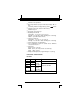
CONTROLS AND INDICATORS 1. DCV Function: Measures DC volts. Auto-ranging from 0 to 600 volts (10 MΩ impedance) 2. ACV Function: Measures AC 26 volts. Auto-ranging from 0 to 21 18 600 volts (10 MΩ impedance) 20 19 15 1 3. Press SEL button (see item 14 2 19) to select desired function: 13 3 17 4 Resistance Function : 12 5 6 Measures resistance. Auto 11 10 7 ranging from 0 to 40MΩ 9 8 (40,000,000Ω). Continuity Function : Tests for continuity be25 24 16 23 22 tween two points.
13. COP RPM Function: Measures RPM on vehicles with “Coil On Plug” ignition systems. One range: 0 to 10,000 rpm. 14. RPM (Tach) Function: Measures RPM. One range: 0 to 10,000 rpm. 15. Dwell Angle Function : Measures dwell angle of breaker points. 16. OFF Function: Turns unit “off” when function is selected. 17. Function/Range Selector Switch: Selects desired function or range. 18. Data HOLD Button: Turns the Data Hold function “on” and “off” (see “Auxiliary Functions” on page 16 for details). 19.
• • To avoid possible electric shock, instrument damage, and/or equipment damage when taking voltage or current measurements, DO NOT exceed the maximum value of the selected range. If the tester is used near high noise Radio Frequency (RF) generating equipment (spark plug wires, ignition coils or alternator), the display may become unstable or indicate large errors. If you obtain erratic readings during use, isolate the tester as far away as possible from these components. TESTING PROCEDURES A.
Ω" jack of the tester; plug 1. Plug the RED test lead into the "Ω the BLACK test lead into the "COM" jack. 2. Set the tester’s Function/Range Selector Switch to the position (see Controls and Indicators, Item 3). 3. Press the SEL button, as necessary, until the (AUTO) icon is shown on the display. NOTE: To obtain accurate readings, disconnect at least one side of the item under test from the circuit or circuit board before measuring resistance. 4.
D. CONTINUITY TEST WARNING To avoid electric shock, shut off the power to the test article before testing it for continuity. 1. Plug the RED test lead into the jack of the tester; plug the BLACK test lead into the "COM" jack. 2. Set the tester’s Function/Range Selector Switch to the position (see Controls and Indicators, Item 3). 3. Press the SEL button, as necessary, until the shown on the display. icon is 4.
2. Set the tester’s Function/Range Selector Switch to the ms position (see Controls and Indicators, Item 5). 3. Place the RED test lead onto the signal output wire of the sensor or circuit under test and the BLACK test lead onto a good chassis ground (consult the wiring diagram in the vehicle’s Service Manual for proper connections). 4. Read the results on the display. G.
I. AC/DC CURRENT MEASUREMENT (AMPS) WARNING To prevent electrical shock when performing current measurements, follow all steps as indicated below DO NOT skip any steps or take any short cuts. The 15A range is not fused. To avoid current hazard and/or damage to the tester, DO NOT try to take measurements on circuits that have more than 15 amps. DO NOT take more than 10 seconds to take the reading. A waiting period of AT LEAST 15 MINUTES is necessary between every 15 second testing period. 1.
J. CLAMP CURRENT MEASUREMENT NOTE: Clamp current measurement requires use of an optional Clamp adapter. The optional Clamp adapter has not been evaluated by UL. 1. Plug the RED test lead from the Clamp adapter to the jack of the tester; plug the BLACK test lead into the "COM" jack. 2. Set the tester’s Function/Range Selector Switch to the position (see Controls and Indicators, Item 11). 3. Clamp the Clamp adapter around the wire or cable from the source or load under measurement. 4.
2. Place the RED test lead onto the “Tachometer Signal port” of the vehicle’s ignition system, or onto the negative (-) side of the ignition coil. Place the BLACK test lead onto a good chassis ground or the negative (-) terminal of the battery. NOTE: If your vehicle is equipped with a COP (Coil On Plug) system and you are using the setting, make the RED test lead connection to the negative (-) side of one of the ignition coils. 3.
1. With the desired value shown on the display, press and hold the HOLD button for approximately two seconds, until the HOLD icon shows on the display. The current value is now “locked” in the display. 2. Press the HOLD button again to turn the function “off.” The HOLD icon will disappear, and the value will no longer be “locked” in the display. NOTE: The data HOLD function is not available for the DIODE TEST, CONTINUITY TEST or PULSE WIDTH MEASUREMENT. B.
• For fuse replacement: Remove the three screws (you must remove the meter stand to remove the third screw) on the back of the meter and separate the case. Remove the fuse from the fuse holder and replace with a 0.500A/250V - UL Listed Bussmann, GMA Type (Radio Shack GMA/270 Series: #270-1047) fuse. NOTE: Use a 0.500A/250V, 5x20mm type fuse ONLY Bussmann, GMA Type (Radio Shack #270-1047 or similar). Using an incorrect fuse may result in serious injury and/or damage to the unit. 3.
19
20
21
LIMITED ONE YEAR WARRANTY The Manufacturer warrants to the original purchaser that this unit is free of defects in materials and workmanship under normal use and maintenance for a period of one (1) year from the date of original purchase. If the unit fails within the one (1) year period, it will be repaired or replaced, at the Manufacturer’s option, at no charge, when returned prepaid to the Service Center with Proof of Purchase. The sales receipt may be used for this purpose.
2005 Instruction MRP #93-0067 E