
Owners manual


Copyright © 2014 IEC. All Rights Reserved.
The Manufacturer warrants to the original purchaser that this unit is free of defects
in materials and workmanship under normal use and maintenance for a period of
one (1) year from the date of original purchase. If the unit fails within the one (1) year
period, it will be repaired or replaced, at the Manufacturer’s option, at no charge,
when returned prepaid to the Service Center with Proof of Purchase. The sales
receipt may be used for this purpose. Installation labor is not covered under this war-
ranty. All replacement parts, whether new or remanufactured, assume as their war-
ranty period only the remaining time of this warranty. This warranty does not apply
to damage caused by improper use, accident, abuse, improper voltage, service, fire,
flood, lightning, or other acts of God, or if the product was altered or repaired by any-
one other than the Manufacturer’s Service Center. The Manufacturer, under no cir-
cumstances shall be liable for any consequential damages for breach of any written
warranty of this unit. This warranty gives you specific legal rights, and you may also
have rights, which vary from state to state. This manual is copyrighted with all rights
reserved. No portion of this document may be copied or reproduced by any means
without the express written permission of the Manufacturer. THIS WARRANTY IS
NOT TRANSFERABLE. For service, send via U.P.S. (if possible) prepaid to
Manufacturer. Allow 3-4 weeks for service/repair.
If you have any questions, require technical support or information on UPDATES and
OPTIONAL ACCESSORIES, please contact your local store, distributor or the
Service Center.
USA & Canada:
(800) 544-4124 (6am - 6pm, GD\VDZHHN PST)
All others: (714) 241-6802 (6am - 6pm, GD\VDZHHN PST)
FAX: (714) - (24 hr.)
Web: www.equus.com
Technical Service Center
17352 Von Karman Ave.
Irvine, CA 92614
LIMITED ONE YEAR WARRANTY AND SERVICE PROCEDURES
GAUGE CONNECTION
4
A. SPEEDOMETER (Figure 4)
Connection of the speedometer requires using the vehicle's existing
speedometer cable. Route existing speedometer cable to rear of speedo-
meter and connect cable to 5/8"–18 male connector on rear of speedome-
ter. If the cable drive and/or the female threaded connector from the vehicle's
speedometer cable does not fit, you must buy an adapter and/or replace the
speedo-meter cable. See IMPORTANT note below. Connection adapters
and cables are available from most speedometer shops.
IMPORTANT: The speedometer is de-
signed for a 1:1 drive ratio (60 mph or
96,5 km/h at 1000 RPM) using a 5/8"-18
cable thread shaft. This shaft requires a
0.104” (2,64 mm) square female cable
drive. If the vehicle’s tire size or differen-
tial ARE NOT stock (original), speedome-
ter accuracy will be affected. It may be
necessary to change to a different pinion
gear to achieve the required 60 MPH at
1,000 RPM.
TRIPMETER OPERATION
The speedometer is equipped with a four-
segment resetable Tripmeter. To reset the
Tripmeter, rotate the Tripmeter reset knob
counterclockwise until the Tripmeter shows "0000".
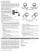
B. HOURMETER / CLOCK (Figure 5)
NOTE: Hourmeter / clock operating voltage is 10 VDC minimum to 80 VDC
maximum (polarity-sensitive).
NOTE: Lead wires must be purchased separately. Use 16 - 18 AWG wire
minimum.
1. Determine routing for gauge lead wires. Use an existing firewall grom-
met, or drill a 3/8" (9.5 mm) hole through firewall to accommodate lead
wires. Install a rubber grommet (purchased separately) in hole, and
use shrink tubing to protect lead wires from chaffing or other damage.
2. Install and crimp or solder 1/4" female spade connectors (purchased
separately) on gauge positive (+) and negative (-) lead wires.
3. Connect lead wires to hourmeter or clock positive (+) and negative (-)
spade posts. Route lead wires through grommet in firewall.
4. Connect free ends of hourmeter or clock lead wires to vehicle electri-
cal system:
HOURMETER
For Negative Ground Systems
■ Connect hourmeter positive lead wire to a switched voltage source
in the vehicle electrical system.
■ Connect hourmeter negative lead wire to a good bare metal chas-
sis ground.
For Positive Ground Systems
■ Connect hourmeter negative lead wire to a switched voltage
source in the vehicle electrical system.
■ Connect hourmeter positive lead wire to a good bare metal chas-
sis ground.
CLOCK
For Negative Ground Systems
■ Connect clock positive lead wire to an unswitched (constant) volt-
age source in the vehicle electrical system.
■ Connect clock negative lead wire to a good bare metal chassis
ground.
For Positive Ground Systems
■ Connect clock negative lead wire to an unswitched (constant) volt-
age source in the vehicle electrical system.
■ Connect clock positive lead wire to a good bare metal chassis
ground.
5. Secure lead wires along their route to prevent damage from sharp
edges, moving parts or hot engine components.
6. Reconnect negative (-) battery cable.
■ For Hourmeter: Start and run engine for several minutes and ver-
ify hourmeter accumulates operating time.
■ For Clock: Observe clock for several minutes and verify time
advances.
EXISTING
SPEEDOMETER
CABLE
Figure 4
TO VO LTAG E
SOURCE
TO VO LTAG E
SOURCE
TO CHASSIS
GROUND
TO CHASSIS
GROUND
NEGATIVE GROUND SYSTEM POSITIVE GROUND SYSTEM
TO
VO LTAG E
SOURCE
TO
VO LTAG E
SOURCE
TO
CHASSIS
GROUND
TO
CHASSIS
GROUND
NEGATIVE GROUND SYSTEM
HOURMETER CONNECTION
CLOCK CONNECTION
POSITIVE GROUND SYSTEM
Figure 5