
Owners manual


INSTALLATION INSTRUCTIONS
SPEEDOMETER / HOURMETER / CLOCK
PREPARATION FOR INSTALLATION
1
Copyright © 2012 IEC. All Rights Reserved. MRP 93-0034 Rev C
1. Read these instructions completely before installing the gauge, and
seek the advice of a professional if you are not familiar with the instal-
lation of vehicle instrumentation or the functions of the related vehicle
systems.
2. Always read the vehicle's service manual and follow its safety pre-
cautions before any test or service procedure is performed.
3. Install gauges only when engine is cool and ignition is off.
4. Disconnect negative (-) battery cable before installing gauges. (Do
not forget to reconnect battery after installation is complete).
NOTE: It may be necessary to reprogram your radio, clock, etc. after
reconnecting the battery.
5. Determine a mounting location for the gauge. Choose a location that
does not impair visibility, or interfere with driving. Check behind the
mounting location for any wiring or components before drilling.
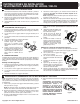
A. SPEEDOMETER / CLOCK (Figure 1)
1. Determine a location on the dashboard that can be cut out without
striking any objects from behind the dash. If an existing hole is already
available for use, proceed to step 3.
2. Using a template, cut out a 3 3/8" (85.7 mm) (or as needed) hole
through the dashboard.
3. Using a round file, smooth out any rough edges around the hole.
4. Insert gauge through front of the hole in dashboard.
5. Hold gauge case and rotate gauge,
as needed, until gauge dial face is
properly positioned in front of dash-
board.
6. Tighten locking ring onto gauge in a
clockwise direction until gauge is
tight against dashboard. Tighten
locking ring HAND TIGHT ONLY.
B. HOURMETER
The hourmeter will use one of two types of mounting options; "In-Dash
Mount" (using a mounting cup) or "Flange Mount." Be sure to use the
installation instructions appropriate to your hourmeter.
Flange Mount (Figure 2)
1. Determine a location on the dashboard that can be cut out without
striking any objects from behind the dash. If an existing hole is already
available for use, proceed to step 3.
2. Using a template, cut out a 2" (50.8 mm) hole through the dashboard.
3. Using a round file, smooth out any rough edges around the hole.
4. Insert gauge through front of the hole in dashboard.
GAUGE INSTALLATION
2
5. Hold gauge case and rotate gauge, as needed, until gauge dial face
is properly positioned in front of dashboard.
6. Using the gauge flange as a tem-
plate, mark the location for three
mounting screws.
7. Using a 1/8" (3.18 mm) drill bit, drill
three holes through the dashboard.
8. Insert gauge through front of the
hole in dashboard, and secure with
three screws, lock washers and nuts
provided. Tighten nuts to 5 inch-
pounds (0.57 Newton-meters).
In-Dash Mount (Figure 3)
1. Determine a location on the dashboard that can be cut out without
striking any objects from behind the dash. If an existing hole is already
available for use, proceed to step 3.
2. Using a template, cut out a 2" (50.8 mm) hole through the dashboard.
3. Using a round file, smooth out any
rough edges around the hole.
4. Insert gauge through front of the hole
in dashboard.
5. Hold gauge case and rotate gauge, as
needed, until gauge dial face is prop-
erly positioned in front of dashboard.
6. Tighten locking ring onto gauge in a
clockwise direction until gauge is tight
against dashboard. Tighten locking
ring HAND TIGHT ONLY
NOTE: Depending on the model of gauge, backlighting color may be
changed to either red, green or blue by installing the optional color filter
over the bulb (not available for all gauge kits).
1. Insert the light bulb and socket assemblies into the light receptacles
on the back of the gauge and press firmly to snap/lock into place.
NOTE: Wire for gauge lights must be purchased separately. Use size 18-
20 AWG stranded copper wire.
2. Splice the RED or WHITE wire from the gauge light(s) into the vehi-
cle's lighting circuit, between the dimmer control switch and the dash
lights (consult the vehicle's service manual for proper wire).
GAUGE LIGHT INSTALLATION AND CONNECTION - Speedometer
3
3. Connect light socket BLACK wire to a
good chassis ground.
4. Insulate all splices and connections with
shrink tubing to prevent shorting.
WARNING: For bulb replacement use only
part # 161 Instrument/Indicator wedge
type bulbs available at most auto parts
stores. DO NOT USE ANY OTHER PART
NUMBER SINCE THE HEAT PRODUCED
BY A HIGHER WATTAGE BULB WILL
MELT THE GAUGE CASE AND CREATE
A FIRE HAZARD.
BULB AND
SOCKET ASSEMBLY
OPTIONAL COLOR
FILTER
Figure 4
4.0
4.0
LOCKING RING
Figure 1
HOURMETER
SCREW
NUT
Figure 2
HOURMETER
LOCKING RING
Figure 3