
Owner manual


INSTALLATION INSTRUCTIONS
AIR / FUEL RATIO GAUGE KITS
PREPARATION FOR INSTALLATION
2
© 2004 IEC - All Rights Reserved MRP #93-0038
1. Read instructions completely before installation. Seek the advice of
a professional if you are not familiar with the installation of vehicle
instrumentation or the functions of related vehicle systems.
2. Install gauges only when engine is cool and ignition is off.
3. Make sure all necessary tools, materials, and parts are on hand.
4. Always read the vehicle's service manual before any test or serv-
ice is performed, and follow it’s safety precautions.
5. Disconnect negative (-) battery cable before installing gauges (do
not forget to reconnect battery after installation is complete).
NOTE: It may be necessary to reprogram your radio, clock, etc. after
reconnecting the battery.
When selecting a location to install the gauge, take into consideration
that the gauge’s signal wires must be routed through the firewall when
making the gauge connections. Choose a location that will allow rout-
ing of the gauge wiring through an existing firewall grommet.
If an existing firewall grommet is not accessible, drill a 3/8” (9,5 mm)
diameter hole through the firewall. Install a rubber grommet (pur-
chased separately) in drilled hole to protect lead wires from chaffing or
other damage.
A. PANEL INSTALLATION
For On-Dash or Under-Dash mounting
(panel is optional with some gauge models
and must be purchased separately).
1. Determine the mounting location for the
gauge.
2. Using gauge panel as a template, mark
locations for screws.
3. Drill small holes for the screws and secure
panel with screws and flat washers provided.
MOUNTING AND INSTALLATION
3
B. IN-DASH MOUNTING OPTION
1. Determine a location on the dashboard that can be cut out without
striking any objects behind the dash.
2. Use a hole template to cut out a 1-1/2", 2" or 2-5/8" (3,81 mm, 5,08
mm or 6,67 mm) hole, as necessary, through the dashboard.
3. Use a round file to smooth out the rough edges around the drilled hole.
C. INSTALLING GAUGE INTO GAUGE PANEL OR IN-DASH
1. Insert gauge through front of panel or
hole in dashboard.
2. Hold gauge case and rotate gauge, as
needed, until gauge face is properly
positioned in front of dashboard/panel.
3. Tighten locking ring on gauge in clock-
wise direction until gauge is tight
against dashboard/panel. Tighten lock-
ing ring HAND TIGHT ONLY.
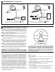
Figure 1. Gauge Panel
LOCKING
RING
Figure 2. Gauge Equipped
with Locking Ring
Install Air/Fuel Ratio Gauge as described in Section 3, MOUNTING
AND INSTALLATION.
Refer to Figure 3 (on back page) and make gauge connections as fol-
lows.
NOTE: Wiring is not provided with gauge kit. Wire and connectors to
suit your particular installation must be purchased separately. Use 20-
22 AWG stranded copper wire.
1. After determining the wire length needed,
2. Crimp or solder ¼" (6,35 mm) female spade terminals (included)
on one end of gauge positive (+) and negative ( ) wires.
3. Connect gauge positive and negative wires to positive (+) and neg-
ative ( ) spade posts.
4. Connect the negative ( ) lead wire to a good (bare metal)
chassis ground.
5. Connect the positive (+) lead wire into a switched (hot only when
the ignition key is turned to the On position) 12 volt positive source.
6. Connect the signal wires (see figure 3) to the Air/Fuel Ratio Gauge
and the vehicle's oxygen sensor(s) SIGNAL circuit(s) as follows:
GAUGE CONNECTION
4
■■
If your vehicle has
only one
pre-catalytic converter oxygen sen-
sor, crimp or solder a wire to the large female spade terminal
(included with gauge kit) and connect the terminal over the two
small male spade signal posts on back of the gauge. Connect
the other end of the wire to the oxygen sensor signal circuit.
This allows the LEDs on both sides of the gauge to display the
air/fuel ratio for one oxygen sensor.
■■
If your vehicle is equipped with two pre-catalytic converter
Oxygen sensors, crimp or solder two wires to the two small
female spade terminals (included in gauge kit), and connect the
terminals to the two small male spade signal posts on back of
the gauge. Splice one of the loose ends of the gauge signal
wires to the signal circuit of the oxygen sensor on Bank 1 of the
engine, splice the other signal wire to the oxygen sensor signal
circuit on Bank 2 of the engine.This allows the LEDs on the right
side of the gauge to display the air/fuel ratio for Bank 1 oxygen
sensor and the LEDs on the Left side of the gauge to display the
Air/Fuel Ratio for Bank 2 oxygen sensor (see figure 3).
CAUTION: Some oxygen sensors use shielded wires. Make your
SIGNAL wire connections on the signal circuit, away from the
shielded wire and after the oxygen sensor connector. DO NOT
make connections on the shielded wire itself.
INTRODUCTION
1
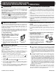
The Air/Fuel Ratio Gauge reads and interprets the voltage output sig-
nals from the vehicle’s oxygen sensor(s) to give an indication of air/fuel
ration while driving; either Optimal, Lean or Rich.
IMPORTANT: The Air/Fuel Ratio Gauge is designed to work with the
vehicle’s existing oxygen sensor.The gauge will work ONL
Y with oxygen
sensors that generate voltage output signals from 0 to 1 volt. See your
vehicle’s service manual for oxygen sensor operating voltage specifica-
tions.
If your vehicle is not equipped with this type of sensor, or is not equipped
with
any
oxygen sensor, it may be possible to install an after-market
heated oxygen sensor. See a professional to determine if a suitable oxy-
gen sensor can be installed on your vehicle.
7.0
7.0