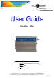
L’esprit Modem User Guide GenPro 25e Reference : EG_GenPro25e_1055_UG_000_UK Revision : 000 Date : 23/01/2014 S.A. ERCO & GENER – ZI de St. Lambert-des-Levées – BP 30163 – F-49412 SAUMUR Cedex Tél. : +33 (0)2 41 83 13 00 – Fax : +33 (0)2 41 67 19 20 – www.ercogener.com – infos@ercogener.com SA CAPITAL 200873 € – R.C.
EG_GenPro25e_1055_UG_000_UK Page 2 / 66 Document History Rev. 000 Modifications Creation Author Date Validation Date YST 23/01/2014 BBO 24/01/2014 The main modifications of this document compared to the previous version are easily identifiable on a screen by the blue color of the text. Descriptions and non-contractual illustrations in this document are given as an indication only. ERCO & GENER reserves the right to make any modification.
EG_GenPro25e_1055_UG_000_UK Page 3 / 66 TABLE OF CONTENTS PRESENTATION............................................................................................................................................... 8 WARNING ......................................................................................................................................................... 9 COPYRIGHT .......................................................................................................................
EG_GenPro25e_1055_UG_000_UK 5.1.5 5.2 7 Hardware reset of the modem ................................................................................................ 25 SPECIFIC RECOMMENDATIONS FOR THE USE OF THE MODEM IN VEHICLES ............................................ 26 5.2.1 Recommended connection on the battery of a truck ........................................................... 26 5.2.2 Technical constraints in trucks ........................................................................
EG_GenPro25e_1055_UG_000_UK 7.6 RESET ........................................................................................................................................... 46 7.6.1 General presentation ............................................................................................................... 46 7.6.2 RESET sequence ..................................................................................................................... 47 7.7 WATCHDOG ...........................
EG_GenPro25e_1055_UG_000_UK Page 6 / 66 INDEX OF TABLES Table 1 : 4-pin Micro FIT connector ............................................................................................................. 16 Table 2 : 2-pin Micro FIT connector ............................................................................................................. 17 Table 3 : 15-pin Sub D HD connector ..........................................................................................................
EG_GenPro25e_1055_UG_000_UK Page 7 / 66 Table 40 : main electrical characteristics of the DS2482S-100 ................................................................. 59 Table 41 : Characteristics of the SIM card power voltage ......................................................................... 60 Table 42 : Conditions of use of the RESET ................................................................................................. 60 Table 43 : Parameters of RF receiver and transmitter .........
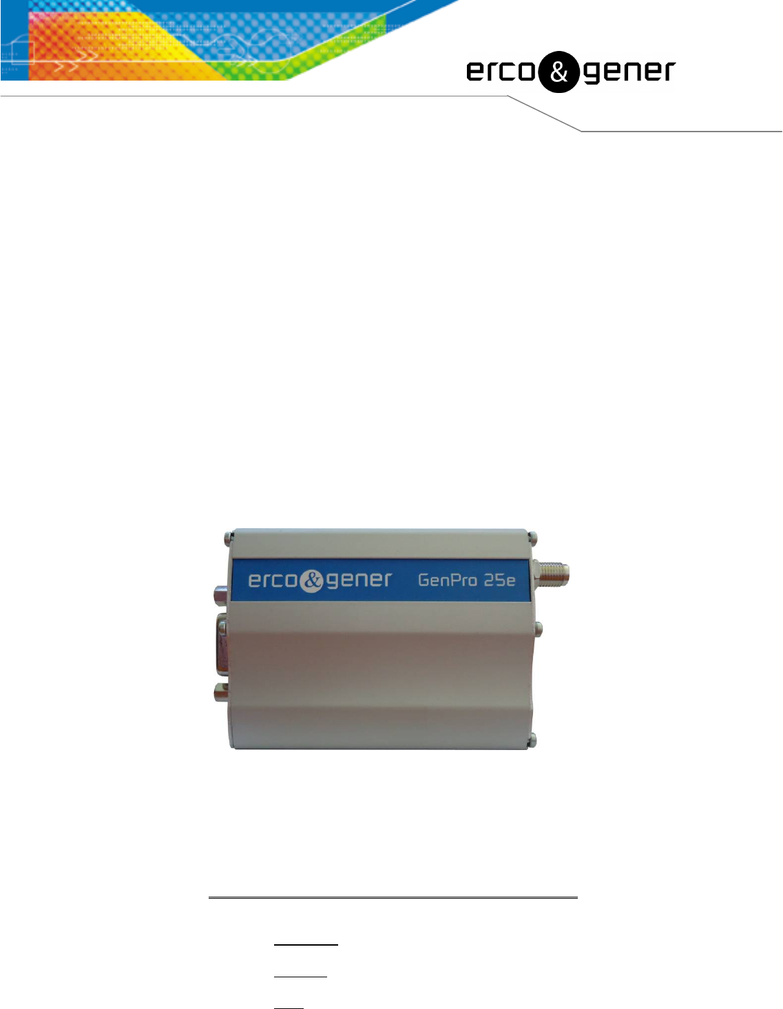
EG_GenPro25e_1055_UG_000_UK Page 8 / 66 Presentation Entirely dedicated for Machine To Machine (M2M) applications and embedded data services, the modem GenPro 25e combines both GSM/GPRS functions in the same robust casing. The modem is Quad-Bands 850/900/1800/1900 MHz and GSM/GPRS Class 10. The GenPro 25e provides 3 operating modes: ▪ Direct mode (transparent mode application): the control is done by an external application.
EG_GenPro25e_1055_UG_000_UK Page 9 / 66 Warning • ERCO & GENER to read carefully all documents linked to the GenPro 25e (User Guide, Application Notes, Command List). • ERCO & GENER cannot be held responsible for: - Problems due to an inappropriate use of the GenPro 25e. - Problems due to a wrong configuration - Problems due to the wrong use of an embedded software application developed or supplied by a third party. - Dysfunctions due to the absence or a bad coverage of the GSM, GPRS networks.
EG_GenPro25e_1055_UG_000_UK Page 10 / 66 Copyright The reproduction, transfer, distribution or storage of part or the totality of the contents of this document, in any form, without the prior written authorization of ERCO & GENER is strictly prohibited. GenPro 25e is a trademark of ERCO & GENER. Hayes is a registered trademark of Hayes Microcomputer Product Inc. The names of products and companies mentioned in this document may be names or trademarks of their respective holders.
EG_GenPro25e_1055_UG_000_UK 1 Page 11 / 66 References 1.1 Referred documents Commands List • AT Command list of the GSM/GPRS module ................. : u-blox_AT_Commands_Manual_xxx.pdf • Embedded application EasePro of ERCO & GENER ..... : EG_EasePro_V2.xx_CL_yyy_UK.pdf Application Notes GenPro 25e of ERCO & GENER ................. : EG_GenPro25e_1055_AN_xxx_yy GSM reference documents: • 3GPP TS 27.
EG_GenPro25e_1055_UG_000_UK FR FTA FTP GCF GND GPIO GPRS GPS GSM HR I IEC IMEI I/O LED LLC MAX ME MIC Micro FIT MIN MNP MO MS MT NOM O Pa PBCCH PC PCL PDP PIN PLMN PUK PWM RF RFI RI RMS RTS RX SIM SMA SMB SMS SNR SNTP SPI SPL SPK SRAM TBD TCP/IP TDMA TU TUHigh Page 12 / 66 Full Rate Full Type Approval File Transfert Protocol Global Certification Forum GrouND General Purpose Input Output General Packet Radio Service Global Positioning System Global System for Mobile communications Half Rate Input Internat
EG_GenPro25e_1055_UG_000_UK Transmit TYPical Universal Time Clock Voltage Stationary Wave Ratio TX TYP UTC VSWR 1.3 Page 13 / 66 Symbols The following symbols are used to highlight the important information of this user guide. A symbol for the essential information about the module integration and performance. A warning symbol indicates the actions that could harm or damage the module 2 Packaging 2.
EG_GenPro25e_1055_UG_000_UK 2.2 Page 14 / 66 Modem packaging The external dimensions of the modem packaging are: - Width ......... : 54.5 mm, - Height ........ : 68 mm, - Length........ : 108 mm. An identification label is placed on the top of the packaging. It shows: - The ERCO & GENER logo, - The product reference: GenPro 25e, - The CE mark, - The IMEI barcode with 15 digits. The dimensions of this label are: - Height ........ : 37 mm, - Length........ : 70 mm. 2.
EG_GenPro25e_1055_UG_000_UK Page 15 / 66 3 General presentation 3.1 Description Description of the modem GenPro 25e, hereunder: 3.1.1 Front side Figure 2 : Front side Connector Micro-Fit 4pts/M Connector Micro-Fit 2pts/M Connector Sub HD 15pts/F 3.1.2 Back side Figure 3 : Back side Connector SMA-F GSM antenna GSM LED SIM card cover 3.1.3 Modem fixing 2 brackets are used to fix the modem on a support.
EG_GenPro25e_1055_UG_000_UK 3.2 Page 16 / 66 External connections 3.2.1 3.2.1.1 Connections Antenna connector GSM antenna connector: The GSM antenna connector is SMA-female with a 50Ω impedance. 3.2.1.2 Micro FIT connectors Female Micro FIT connector with 4 male pins: This connector of the GenPro 25e is used for the DC external power supply and the GPIOs (the 2 signals Input and Output).
EG_GenPro25e_1055_UG_000_UK Page 17 / 66 Female Micro FIT Connector with 2 male pins: This connector of the GenPro 25e is used for the GPIO (2 Inputs signals).
EG_GenPro25e_1055_UG_000_UK 3.2.1.3 Page 18 / 66 15-pin Sub D HD connector The female 15-pin high density Sub D connector is used for: - The RS232 serial link connection, - The audio line connection (microphone and loudspeaker), - The BOOT and RESET signals.
EG_GenPro25e_1055_UG_000_UK 3.2.2 3.2.2.1 Page 19 / 66 Cables 4-wire micro FIT cable The 4-wire micro FIT cable is used to supply power to the modem and to use the 2 signals Input and Output. Figure 8 : 4-wire Micro FIT cable Figure 9 : 4-wire Micro FIT cable connector Vue from pin side Table 4 : Characteristics of the 4-wire Micro FIT cable Component Characteristics 4-pin Micro FIT connector Supplier : MOLEX Cable Length ≈ 1.5m Wire Tinned copper 24 x 0.2 mm Section : 0.
EG_GenPro25e_1055_UG_000_UK Page 20 / 66 Figure 10 : Fuse Mini Blade for vehicle 3.2.2.2 2-wire micro FIT cable The 2-wire micro FIT cable allows to use the 2 additional Inputs. Figure 11 : 2-wire Micro FIT cable Figure 12 : 2-wire Micro FIT cable connector Vue from pin side Table 5 : Characteristics of 2-wire Micro FIT cable Component Characteristics 2-pin Micro FIT connector Supplier : MOLEX Cable Length ≈ 1.5m Wire Section : 0.
EG_GenPro25e_1055_UG_000_UK Page 21 / 66 4 Characteristics and Services The GenPro 25e is a modem GSM/GPRS class10 dedicated to the transmission of binary data in asynchronous, SMS, Voice and Fax Group 3 Class 2.0.
EG_GenPro25e_1055_UG_000_UK Page 22 / 66 5 Use of the modem 5.1 5.1.1 Starting with the modem Assembly of the modem To place the modem on a support, use the fixing brackets as indicated on the scheme below. Figure 13 : Assembly of the modem - Must be fixed on a flat surface. - Max. height of the screw head : 2 mm. The aluminum casing of the modem is connected to the 0V (GND) of the power supply and to the 0V of the RS232 serial link.
EG_GenPro25e_1055_UG_000_UK 5.1.2 Page 23 / 66 Installation of the modem To install the modem, it is recommended to do the following operations with the modem turned OFF: - Remove the SIM card cover on the back side. - Carefully insert the SIM card in the reader. Figure 14 : Insertion SIM card Way of insertion of SIM card - Push the SIM card until hearing a "clic" that ensures its correct positioning. - Put the SIM cover back. - Connect the GSM antenna to the SMA-F connector.
EG_GenPro25e_1055_UG_000_UK 5.1.3 5.1.3.1 Page 24 / 66 Checking the communication with the modem Without library The GenPro 25e does not contain any library, it will return the menu of the Bootloader. Connect the RS232 link between the DTE (the COM port) and the modem (DCE). Configure the RS232 port of the DTE as follows: ▪ Bits per second ..... : ▪ Data Bits ................ : ▪ Parity ..................... : ▪ Stop Bits ................ : ▪ Flow control ...........
EG_GenPro25e_1055_UG_000_UK Page 25 / 66 With this status, the two leds are OFF. In the case where no communication can be established with the modem: ▪ Check the RS232 connection between the DTE and the modem (DCE), ▪ Check the configuration of the COM port of the DTE. 5.1.3.3 The ERCO & GENER application EasePro-V2.xx The GenPro 25e contains the application EasePro_V2.xx. Send the command ATI8. The modem returns the version (example of display) EasePro V2.
EG_GenPro25e_1055_UG_000_UK 5.2 Page 26 / 66 Specific recommendations for the use of the modem in vehicles The power supply connector of the modem GenPro 25e must NOT be directly connected to the battery of the vehicle. 5.2.1 Recommended connection on the battery of a truck All trucks have a Circuit Breaker outside the cabin.
EG_GenPro25e_1055_UG_000_UK 5.2.2 Page 27 / 66 Technical constraints in trucks It is highly recommended NOT to connect the modem supply directly to the battery but to the circuit breaker. Otherwise the modem can be damaged when the truck is starting up if the circuit breaker is closed (in this case, the ground of the truck and the ground of the battery will be connected via the modem as described in the scheme below).
EG_GenPro25e_1055_UG_000_UK 5.3 GSM led of the modem 5.3.1 Without EGM application Page 28 / 66 The GenPro 25e does not contain any library. Only Boot Loader menu is displayed. The led is OFF. 5.3.2 With the transparent mode application The yellow led is directly driven by the GSM/GPRS module. 5.3.
EG_GenPro25e_1055_UG_000_UK 5.4 The Page 29 / 66 Echo function of AT commands deactivated modem contains the transparent mode application (see the documents "ublox_AT_Commands_Manual_xxx.pdf"; in this case, if no echo is returned when entering an AT command, it means that: - the "local echo " of your communication software (like Hyperterminal) is not activated, - the echo function of the modem has been deactivated.
EG_GenPro25e_1055_UG_000_UK Page 30 / 66 Table 8 : RSSI value value Gain in dbm Interpritation value 0 -113 dbm Insufficient 0 to 7 1 to 10 -111 to -95 dbm Insufficient 11 to 30 -93 to -53 dbm Sufficient 31 (max) -51dbm Perfect 99 Unknown/not detectable 99 Interpretation See Standards ETSI GSM 05.08 Unknown/not detectable The GSM modem works normally with a minimum between 11 and 15.
EG_GenPro25e_1055_UG_000_UK 5.7 Page 31 / 66 Verification of modem registration on GSM network 1. Ensure that a valid SIM card has been inserted in the SIM card reader of the modem. 2. Using a communication software like HyperTerminal, enter the following AT commands: a. AT+CPIN="xxxx" to enter the PIN code. The user has only 3 attempts to enter the PIN code. After the third attempt, only a second code (PUK code) supplied by the operator, will allow you to choose a new PIN code. b.
EG_GenPro25e_1055_UG_000_UK 5.8 Page 32 / 66 Verification of modem registration on GPRS network 1. Ensure that a valid SIM card has been inserted in the SIM card reader of the modem. 2. Using a communication software like HyperTerminal, enter the following AT commands: a. AT+CPIN="xxxx" to enter the PIN code. The user has only 3 attempts to enter the PIN code. After the third attempt, only a second code (PUK code) supplied by the operator, will allow you to choose a new PIN code. b.
EG_GenPro25e_1055_UG_000_UK 5.9 The Page 33 / 66 Verification of internal voltages of the modem modem contains the application EasePro V2.xx (see the documents EG_EasePro_V2.xx_CL_yyy_UK.pdf) Two commands allow reading the internal voltages of the modem. • The input of the DC/DC converter +V DC • The battery voltage if this option is present +V INTERNE Figure 17 : Internal voltages of the modem 5.9.
EG_GenPro25e_1055_UG_000_UK 5.9.2 Page 34 / 66 Reading the internal voltage +V INTERNE The command AT+EGADC=3 allows to read the power supply voltage +V INTERNE of the modem. This voltage is measured in mV DC . Table 12 : Reading the internal voltage +V INTERNE Standard This measure corresponds to the output voltage of the DC/DC converter +V INTERNE ≈ 3.
EG_GenPro25e_1055_UG_000_UK Page 35 / 66 5.10 Main AT commands (HAYES) The modem contains the EGM standard library (see the documents "EG_EGM_CL_xxx_yy" of ERCO & GENER); in this case, the table below shows the main AT commands necessary for the control of the modem. Other AT commands are available, see the document "u-blox_AT_Commands_Manual_xxx.pdf".
EG_GenPro25e_1055_UG_000_UK Page 36 / 66 5.11 Turning OFF the modem The modem contains the EGM standard library (see the documents "ublox_AT_Commands_Manual_xxx.pdf"); in this case, it is strongly advised to un-register from the network with the command AT+COPS=2.
EG_GenPro25e_1055_UG_000_UK Page 37 / 66 6 Trouble Shooting This section of the document describes the problems that may be encountered when using the modem. 6.1 Problem of communication between the modem and the RS232 link (V24) If the modem does not respond to the AT commands via the RS232 link, see the table below for the possible causes and the solutions. Table 14 : Solutions when there is no dialogue between the modem and the RS232 link If the modem...
EG_GenPro25e_1055_UG_000_UK 6.2 Page 38 / 66 "ERROR" message The modem returns a message "ERROR" (in response to an AT command) in the following cases: ▪ The COM port is not directed to the modem GenPro 25e but to another modem. Enter ATI0, the response must be "LEON-G100-xxx-yy". Any other response indicates a dialog with another modem. In this case, check the COM port used in Hyperterminal.
EG_GenPro25e_1055_UG_000_UK 6.3 Page 39 / 66 "NO CARRIER" message If the modem returns the message "NO CARRIER" after an attempted call (voice or data), see the table below for the possible causes and their solutions. Table 15 : Solutions when a message "NO CARRIER” is returned If the modem...
EG_GenPro25e_1055_UG_000_UK Page 40 / 66 7 Functional description 7.1 Architecture Figure 18 : Functional architecture 7.2 7.2.1 Power supply General presentation The modem must be powered by an external DC voltage (+V DC ) between: Table 16 : Power supply range Standard +6.5V ≤ +V DC ≤ +32V With battery option +7.2V ≤ +V DC ≤ +32V The regulation of the modem power supply is made with a DC/DC internal converter in order to supply all necessary internal DC voltages.
EG_GenPro25e_1055_UG_000_UK 7.2.2 Page 41 / 66 Internal battery option The battery is fixed inside the GenPro 25e. It is connected to an additional charging circuit cabled on the mother board of the GenPro 25e. This battery allows to maintain the GenPro 25e functioning in case of absence of its external power supply (power supply connected on the Micro-FIT 4-pin female connector). The internal charging circuit allows to keep permanently the charging of the battery from the external power supply.
EG_GenPro25e_1055_UG_000_UK 7.2.2.2 Page 42 / 66 Charge voltage and power supply voltage The following table shows the consumptions of the modem when the GSM antenna and the SIM card are present. These values were measured after a complete discharge of the battery. Table 18 : Consumption of power supply (2*) GSM CONDITIONS T=25°C External supply voltage I Charge Nom.(mA) Without RS232 @ 7.
EG_GenPro25e_1055_UG_000_UK 7.2.2.4 Page 43 / 66 Instructions and restrictions of use The internal battery option is not cabled by default and its implementation must be made by ourselves in our factory (contact us). When the battery is completely discharged, it takes around three hours to obtain a complete charge. When the battery is present and charged, the fact of removing the power supply +V DC does not turn OFF the equipment. For this, see §5.11 Turning OFF the modem.
EG_GenPro25e_1055_UG_000_UK Page 44 / 66 Figure 19 : Normalized signals of a RS232 serial link The RS232 interface was designed to allow certain flexibility in the use of the serial interface signals. In fact, after the setting (see command AT+IFC), the modem can work in 3-wire mode (using only the signals TX, RX, GND), but the use of the signals TX, RX, GND, CTS, RTS is required for a GPRS application, which is not the case for the signals DTR, DSR, DCD and RI which may not be used. 7.3.
EG_GenPro25e_1055_UG_000_UK 7.4 Page 45 / 66 Inputs/Output functioning The modem contains an EGM application: in this case, the modem GenPro 25e provides 3 inputs (optocoupled) and 1 output (open collector) available for an external use. These functions can also be controlled by AT commands: AT+GPIOSET for a writing access to a GPIO with the GPIO used as an output, AT+GPIOGET for a reading access to the GPIO with the GPIO used as an input. 7.4.
EG_GenPro25e_1055_UG_000_UK 7.5 Page 46 / 66 BOOT This signal must NOT be connected, NOT used. Its use is strictly reserved for the manufacturer. 7.6 RESET 7.6.1 General presentation This signal allows performing a Hardware RESET of the modem. In fact, this pin is used to force a RESET of the modem by putting it downwards during at least 10 ms. This signal must be used only in case of emergency RESET.
EG_GenPro25e_1055_UG_000_UK 7.6.2 Page 47 / 66 RESET sequence To activate the emergency RESET sequence, the RESET signal must be put downwards during at least 10 ms. As soon as the modem has been RESET, if a SIM card is inserted inside the SIM reader, you must wait for the end of the initialization before accessing it again. Figure 20 : RESET sequence Using the RESET does not restore the factory parameters. 7.
EG_GenPro25e_1055_UG_000_UK 7.8 Page 48 / 66 Audio The modem contains the transparent mode application. The audio interface is standard to connect an equipment like a telephone handset. The echo cancelation (command AT+UMGC) and noise reduction features are also available in order to improve the audio quality in the case of free-hand applications.
EG_GenPro25e_1055_UG_000_UK 7.8.1 Page 49 / 66 Microphone inputs The microphone inputs are assembled in differential to reduce the noise in common mode and the TDMA noise. They already include the functionality for a microphone like Electret (0.5 mA and 2 Volts) and they are ESD protected. This Electret microphone can be directly connected to these inputs allowing an easy connection to a telephone handset. The microphone impedance is around 1.5 kΩ.
EG_GenPro25e_1055_UG_000_UK 7.9 Internal processor 7.9.1 EGM presentation Page 50 / 66 The GenPro 25e has an ARM7 processor that allows to have an embedded application developed from the EGM libraries and based upon eCos. The EGM libraries supplied by ERCO &GENER contain the following elements: ● EGM software library, ● eCos software library, ● A set of header files (.h) defining the EGM API functions, ● Source code samples. 7.9.
EG_GenPro25e_1055_UG_000_UK Page 51 / 66 8 Technical characteristics 8.1 Mechanical characteristics Table 27 : Mechanical characteristics Dimensions 73 x 54.5 x 25.5 mm (excluding the connectors) Complete dimensions 88 x 54.5 x 25.5 mm ≈ 88 grams (modem only) < 190 grams (modem + brackets + cables) 101.5 cm³ Aluminium profile IP31 Weight Volume Casing Waterproof class The illustration below shows the dimensions of the modem including the clearances necessary for the installation of the modem.
EG_GenPro25e_1055_UG_000_UK Page 52 / 66 If the battery option is present, prepare the modem for storage or transport phases in order to limit high discharges of the battery. For that, see the 5.11 Turning OFF the modem The following table describes the consequences of over-voltage or insufficient voltage on the modem. Table 29 : Effects of power supply defect Then: ▪ Voltage falls below 6.
EG_GenPro25e_1055_UG_000_UK Page 53 / 66 Table 32 : GSM module consumption @ 25 °C GSM module Band V IN Low consumption Mode Average I Nominal Unit. 6.5 12 24 32 V 0,1 0,1 0,03 0,02 mA @ DRX = 5 1,4 0,9 0,5 0,4 mA @ DRX = 9 0,9 0,6 0,32 0,26 mA 2184 1065 504 374 mA 850 / 900 MHz (P = 32.2 dBm typ.) 212 115 60 47 mA 1800 / 1900 MHz (P = 29.2 dBm typ.) 177 96 50 39 mA 850 MHz (P = 30.5 dBm typ.) 290 158 81 63 mA 900 MHz (P = 30.5 dBm typ.
EG_GenPro25e_1055_UG_000_UK 8.2.4 Page 54 / 66 Audio interface The audio interface is available via the 15-pin Sub HD connector, see the § 3.2.1.3 15-pin Sub D HD connector . Main AT commands to control the audio string. • AT+UHFP: Hand Free Parameters • AT+UMGC: Microphone Gain Control • AT+USGC: Speaker Gain Control • AT+USTN: Sidetone • AT+USPM: Audio Path mode setting • AT+USTN: Sidetone Descriptions and non-contractual illustrations in this document are given as an indication only.
EG_GenPro25e_1055_UG_000_UK 8.2.4.1 Page 55 / 66 Microphone The microphone input is designed for a direct connection of the electret condenser micro. (For more details, see the command AT+USPM).
EG_GenPro25e_1055_UG_000_UK 8.2.4.2 Page 56 / 66 Loudspeaker By default, the loudspeaker output is not active. For more details, see the command AT+USPM. This output corresponds to SPK_P and SPK_N of the documentation.
EG_GenPro25e_1055_UG_000_UK 8.2.5 Page 57 / 66 Inputs/Output By default, the GenPro 25e provides 3 opto-coupled inputs (I1 to I3) and 1 open-collector output (O1). As an option, it is possible to have an analog input instead of the opto-coupled input I2. 8.2.5.1 Opto-coupled inputs (I1, I2, I3) Table 36 : Diode characteristics of opto-coupled inputs Characteristics Symbols Max. current Conditions Max. Unit I F (rms) 50 mA Max.
EG_GenPro25e_1055_UG_000_UK 8.2.5.2 Page 58 / 66 Output (S1) Table 37 : Characteristics of open-collector output Characteristics Symbols Conditions Max. Unit Max. voltage V CE0 Transmitter open 48 V DC Max. voltage V CES V BE = 0 V 48 V DC Collector current IC 0.5 A Saturation voltage V CEsat I C = 500 mA 1.3 V Dissipation P Ttot T amb ≤ 25 °C, T j = 110 °C 0.78 W Figure 27 : Electrical scheme of the output No protection is provided.
EG_GenPro25e_1055_UG_000_UK 8.2.5.4 Page 59 / 66 Analog Input – ANA1 (4 – 20mA) on INPUT 2 As an option, it is possible to have an analog input instead of the opto-coupled input I2. This analog input allows to do a current measure (contact us). Table 39 : Characteristics of the option Analog Input 1 in current Characteristics Symbols Analog input ANA1 Conversion range Conditions Min. 6.5 V ≤ +V DC ≤ 32V Typ. 0.66 Polarization current Max.
EG_GenPro25e_1055_UG_000_UK Page 60 / 66 For more information, see the manufacturer documentation. http://datasheets.maxim-ic.com/en/ds/DS2482-100.pdf Figure 30 : Internal electrical scheme of the bus One Wire multi salves The integrator has the responsibility to protect the input from electric disturbances and to respect the values of the functioning parameters. 8.2.6 SIM interface Table 41 : Characteristics of the SIM card power voltage 8.2.7 Component Value SIM Card 3 V or 1.
EG_GenPro25e_1055_UG_000_UK 8.2.8 Page 61 / 66 RF GSM/DCS characteristics 8.2.8.1 RF functioning The RF functioning complies with the recommendation ETSI GSM Standard. The RF performances for the receiver and the transmitter are described below.
EG_GenPro25e_1055_UG_000_UK 8.2.9 Page 62 / 66 Characteristics of the serial link (UART) Table 45 : Characteristics of the UART Characteristics Symbols Conditions Min. Input Voltage – Range V Input Input Voltage – Range -25 Input Voltage – Low V IL Input Voltage – Low 0.4 Input Voltage – High V IH Input Voltage – High 2 Input Hysteresis V Hys Input Hysteresis 0.
EG_GenPro25e_1055_UG_000_UK 8.4 Page 63 / 66 Standards/Conformities The product complies with the following requirements: - R&TTE 1999/5/EC Directive, - EN301489-1:V1.8.1 - EN301489-7:V1.3.1 - §6.5, §6.6, §6.8 and §6.9 of the 2004/104/CE directive - EN 301 511 v9.0.2 - EN 60950-1:2006 + A11:2009 - ROHS Compliant : Directive 2002/95/CE - "REACH" N°1907/2006 - 2002/96/CE DEEE (Crossed-out wheelie bin). The following marking appears under the device.
EG_GenPro25e_1055_UG_000_UK Page 64 / 66 9 Security recommendations 9.1 General security It is important to respect the specific regulations regarding the use of radio equipment, in particular with the possible risks of interference due to radio frequency (RF). Please respect carefully the following security advices. Turn OFF your GSM modem: ● On an aircraft, the use of cellular telephones can endanger the plane operations; disturbing the cellular network is illegal.
EG_GenPro25e_1055_UG_000_UK 9.2 Page 65 / 66 Security in a vehicle Do not use your Modem whilst driving, unless equipped with a correctly installed ear-piece/hands-free kit. Respect the national regulations regarding the use of cellular telephones in vehicles. Road safety is always a priority. An incorrect installation of the GSM modem in a vehicle could cause an incorrect functioning of the vehicle’s electronics. To avoid such problems, ensure that the installation was done by a qualified person.
EG_GenPro25e_1055_UG_000_UK Page 66 / 66 10 Recommended accessories The accessories recommended by ERCO & GENER for the modem GenPro 25e are described on our website in the section Products/Accessories. For more information, contact our sales department. 11 Client support ERCO & GENER ensures the client support for all its modems sold.