TV Wall Mount Instruction Manual V1.0 Model: EI6121 Thank you for choosing this ERGO-INNOVATE product! At ERGO-INNOVATE we strive to provide you with the best quality products and services in the industry. Should you have any issues, please don't hesitate to contact at support@ergo-innovate.com.
IMPORTANT SAFETY INFORMATION • Please carefully read all instructions before attempting installation. If you do not understand the instructions or have any concerns or questions, please contact our customer service at support@ergo-innovate.com. CAUTION: Avoid potential personal injuries and property damage! • Do not use this product for any purpose that is not explicitly specified in this manual. Do not exceed weight capacity.
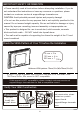
Tools Needed (Not lncluded) Stud Finder Tape Measure 5/32 in.(4 mm) Wood Drill 3/8 in.(10mm) Concrete Drill Hammer Pencil 3/8in.(10mm) Socket Wrench Drill Phillips Screwdriver Level Awl Supplied Parts and Hardware Warning: This product contains small items that could be a choking hazard if swallowed. Before starting assembly, verify all parts are included and undamaged. Do not use damaged or defective parts. lf you require replacement parts, contact our customer service at support@ergo-innovate.
Supplied Parts and Hardware for Step 2 Washers 04 05 Spacers [If needed] Note: The washers and spacers are shown in accordance with the actual size [B1] x4 [B2] x4 M4/M5 M6/M8 06 [C1] x4 φ8.5x18x2.5mm TV Bolts [C2] x4 φ8.
Supplied Part and Hardware for Step 3 03 x1 Arm Assembly/Wall Plate Note: The lag screw is shown in accordance with the actual size x2 A1 Lag Screw ST6x60mm CAUTION! A2 x2 Wall This anchor is for conAnchor φ10X50mm crete or brick walls ONLY. DO NOT use them in drywall or wood studs.
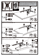
Attach the extender brackets to faceplate using 4 pcs bolts [E1] and 4 pcs nuts [E2] for pattern [B] and [C]. Note: The small bump on the extender bracket [02] should be aligned with the hole on the faceplate [01]. B C E1 01 01 02 E1 E2 02 E2 Step 2 Secure the Faceplate [01] or Faceplate [01] with Extender Brackets [02] to TV Select TV Bolts Only one bolt size fits your TV. M4 M6 M8 Bolt length: Verify adequate thread engagement with bolts or bolts/spacers combination.
CAUTION: Ensure the faceplate [01] or faceplate [01] with extender brackets [02] is EQUALLY CENTERED on your TV AND securely fastened in place. UP Option A (For Flat Back TV) 05 D1/D3/D5 03 B1/B2 04 C1 (If needed) Option B (For Round Back TV) 06 D2/D4/D6 04 B1/B2 05 C1/C2 Alternate Spacer Setups Option C (For TV with A “Bump”) Spacers may be necessary for 2 holes ONLY.
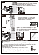
Option D For cable interference or inset holes, use spacers 05 to create extre space between the TV and faceplate(or faceplate with extender) )bracket. 05 C1/C2 06 D2/D4/D6 04 B1/B2 Alternate Spacer Setups Step 3 Attach the Arm Assembly/Wall Plate [03] to Wall For wood stud installation, follow STEP 2A For concrete installation, follow STEP 2B Step 3A Wood Stud Option WARNING: ●Avoid potential personal injury or property damage! DO NOT over-tighten the lag screws [A1].
3A-2 03 Position the arm assembly/wall plate [03] at your desired height and line up the holes with your stud center line. Level the arm assembly/wall plate [03] and mark the holes. UP 3A-3 Drill 2 pilot holes using a 5/32 in.(4 mm) diameter drill bit. Make sure the depth is not less than 2 23/64 in.(60mm). 2 23/64 in.(60mm) ø5/32 in.(4mm) 3A-4 Install the arm assembly/wall plate [03] using lag screws [A1] .
3B-1 03 Position arm assembly/wall plate [03] at your desired height, level the wall arm assembly/wall plate [03] and mark the pilot hole locations. UP 3B-2 Drill 2 pilot holes using a 3/8 in.(10mm) diameter drill bit. Make sure the depth is not less than 2 9/16 in.(65mm). Never drill into the mortar between blocks. 2 9/16 in.(65mm) ø3/8 in.(10mm) 3B-3 Use the hammer to knock anchors [A2] into the wall. Be sure the anchors [A2] are seated flush with the concrete surface.
Step 4 Secure the TV onto the Arm Step 4-1 Remove the preassembled bolts [T] and washers [W] from the arm, and keep them for the use in step 4-3 W T Step 4-2 Hang the TV to the arm. Step 4-3 Tighten the bolts [T] and washers [W] to secure TV to the arm. T w HEAVY! You may need assistance with this step. Step 5 Tilt Adjustment 1. Slightly loosen both tilt bolts [T] slightly. 2. Adjust TV to your desired tilt angle. 3. Retighten both tilt bolts [T] to fix the tilt angle.
Step 6 Level Adjustment 1. Slightly loosen the preassembled bolt [L] using wrench. 2. Level your TV. 3. Retighten the preassembled bolt [L] using wrench to secure the TV in place. L Note: Please do not-over-tighten or over-loosen the bolt [L]. Thank you again for choosing this ERGO-INNOVATE product! All of us at ERGO-INNOVATE do appreciate your product purchase. We hope that you are as happy with your product as we are designing and manufacturing it for you.