.32-.36 AND .46 ASSEMBLY INSTRUCTIONS ERGO SPECIFICATIONS Overall Length 46.5" Tail Rotor Diameter 9.17" Overall Height 16.38" Gear Ratio 9.78:1:5.18 Main Rotor Diameter 48.5" (.32-.36) 50" (.46 3D) Gross Weight 6.75-7.0 lbs.
INTRODUCTION Congratulations on your purchase of the JR Ergo helicopter kit. models. For further information, you can contact the AMA at: This kit has been both engineered and manufactured by JR with help from some of Japan’s top R/C helicopter engineers (now employed by JR).
INDEX Section Description Tools Page Section Description . . . . . . . . . . . . . . . . . . . . . . . . . . . . . . . . . . . . . . . . . . . . .4-6 5-2 Tail Gear Case Assembly . . . . . . . . . . . . . . . . . . . . . . . . .27 Hardware Identification . . . . . . . . . . . . . . . . . . . . . . . . . . . . . . . . . . . .7 5-3 Tail Center Hub Assembly . . . . . . . . . . . . . . . . . . . . . . . .28 1-1 Clutch Bell/Start Shaft Assembly . . . . . . . . . . . . . . . . . . . .
ERGO .32-.36 AND ERGO .46 3D FEATURES Heavy-Duty Aluminum Quad Frame System Provides excellent rigidity and vibration absorption. Straight Blade Axle Rotor Head Design Provides high responsiveness and solid blade tracking. One-Way Hex Start Shaft System Provides positive starting. Starter shaft utilizes a one-way bearing that allows the shaft to stop after the engine is started. Low Drag Flybar Paddles Provide quick yet smooth cyclic response at all flight speeds.
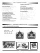
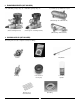
2. ENGINE REQUIREMENTS (NOT INCLUDED): A .32-.36 R/C Helicopter Engine (Ergo .30) or .46 R/C Helicopter Engine (Ergo .46) A special helicopter type muffler is also required (JRP960078 Ergo .32-.36 Muffler Shown) (Webra .33 Heli Engine Shown) (Thunder Tiger Pro .46 Heli Engine Shown) (JRP960079 Ergo .46 Muffler Shown) 3.
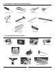
4. TOOLS NEEDED TO ASSEMBLE THE JR ERGO (NOT INCLUDED): Nut Drivers: 5mm, 7mm Phillips Screwdirver Drill and Drill Bits Needle Nose Pliers Scissors Metric Ruler X-Acto Knife Small Hammer Blade Balancer Allen Wrenches: 1.5, 2.0, 2.5, 3.0mm 5. FIELD EQUIPMENT REQUIRED (NOT INCLUDED): 12 Volt Starting Battery 12 Volt Electric Starter Helicopter Fuel 15% - 30% Pitch Gauge 1.
HARDWARE IDENTIFICATION There are many various sizes and shapes of hardware included in this kit. Prior to assembly, please be careful to identify each screw by matching it to the full size screw outlines included in each step. C A C A B Self Tapping Screw 3mm Flat Washer B 2.
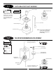
1-1 CLUTCH BELL/START SHAFT ASSEMBLY Starter Hex Adaptor ..........1 pc Complete Assembly 3x4mm Set Screw Use Threadlock * When installing the Start Shaft Bearing Block Assembly, be sure the Bearing Block is positioned so the Bushing faces upward toward the starter hex adaptor, with the bearing toward the Clutchbell Assembly.
1-3 CONTROL BALL INSTALLATION Mixing Lever (3 pc) (Prepare 3 Sets) 2x8mm Flat Head Screw Use Threadlock ........1 pc 2x8mm Flat Head Screw 2mm Nut Roll Bell Crank ........8 pc Steel Joint Ball 2x10mm Flat Head Screw 2mm Nut Steel Joint Ball ........9 pc Steel Joint Ball ........3 pc 2mm Nut 2x10mm Flat Head Screw (8 pc) Mixing Base Arm (Collective) Joint Ball (9 pc) 1-4 2x10mm Flat Head Screw SERVO MIXING LEVER UNIT ASSEMBLY Complete Assembly ........2 pc Use Threadlock ........
1-5 ELEVATOR ARM ASSEMBLY Elevator Arm Rear Elevator Arm Front ..........2pc Swashplate A Arms 2x8mm Flat Head Screw ......2pc Steel Joint Ball Elevator Arm Pin ......2pc Steel Joint Ball Steel Joint Ball 2x8mm Flat Head Screw 2x8mm Flat Head Screw Elevator Arm Pin Caution: Be sure to note correct Swashplate A Arm installation direction. Swashplate A Arm Swashplate A Arm Elevator Arm Swashplate A Arm Elevator Arm (Rear) Elevator Arm (Front) 1-6 Tap-in gently with a small hammer.
2-1 UPPER MAIN FRAME SECTION ASSEMBLY Upper Main Shaft Bearing Block Use Threadlock On All Screws Bearing Flush with Flange UP ..........21 pc Bearing 3x8mm Socket Head Bolt Position so the side of the bearing block that has the bearing flush with the flange is upward. Lower Main Shaft Bearing Block ..........1 pc 3x10mm Socket Head Bolt UP Bearing Flush with Flange ..........
2-2 UPPER MAIN FRAME CONTROL LEVER INSTALLATION Use Threadlock Note: Be sure to install the Elevator Arm Units in their proper location as there is a “Front” and a “Rear” Unit (Step 1-5). Elevator Arm Bushing Nylon Washer Nylon Washer Elevator Arm Bushing 3x8mm Socket Head Bolt Nylon Washer 3x6mm Socket Head Bolt 3x8mm Socket Head Bolt Nylon Washer Roll Bellcrank Spacer 3x22mm Socket Head Bolt Mixing Base Nut ........2 pc 3x6mm Socket Head Bolt 3x6mm Socket Head Bolt ........
2-3 LOWER MAIN FRAME ASSEMBLY Lower Main Frame 2.6x8mm Self Tapping Screw (4 pc) ........ 4pc 3x8mm Socket Head Bolt ........4 pc 3mm Lock Nut ........4 pc 3mm Lock Nut (4 pc) 2.6x8mm Self Tapping Screw Lower Frame Angle (2 pc) 2.6x8mm Self Tapping Screw Servo Mounting Plate 3x8mm Socket Head Bolt (4 pc) 2-4 FUEL TANK INSTALLATION Note: Install the Fuel Tank and Tank Mounting Rubber into the lower frame halves before attaching the Main Frame Standoffs.
2-5 FRONT RADIO BED/GYRO MOUNTING PLATE INSTALLATION Gyro Mounting Plate ........6 pc Use Threadlock 3x10mm Socket Head Bolt Front Radio Bed ........2 pc 3x18mm Set Screw Body Mounting Standoff Long ........2 pc Body Mounting Standoff Long 3x10mm Socket Head Bolt (6 pc) 3x18mm Set Screw (2 pc) Body Mount Standoff, Long 3x10mm Socket Head Bolt 2-6 COOLING FAN SHROUD INSTALLATION Cooling Fan Shroud ........4 pc 2.6x8mm Self Tapping Screw Ergo .46 Fan Shroud Adjustment 2.
2-7 3x22mm Socket Head Bolt UPPER/LOWER MAIN FRAME ASSEMBLY ATTACHMENT ........12 pc Main Frame Standoff, 32mm ........6 pc Main Frame Spacer, 12.5mm ........12 pc Use Threadlock On All Screws Main Frame Spacer, 12.
3-1 MAIN DRIVE GEAR/AUTOROTATION ASSEMBLY 3x6mm Socket Head Bolt (4 pc) [Tighten equally to prevent warping of Main Drive Gear] Use Threadlock Main Drive Gear .......4 pc 3x6mm Socket Head Bolt Autorotaion Assembly 3-2 MAIN DRIVE GEAR/AUTOROTATION ASSEMBLY INSTALLATION Main Shaft Collar Use Threadlock 4x4mm Set Screw (4 pc) 8mm ........4 pc 4x4mm Set Screw Main Rotor Shaft 3x22mm Socket Head Bolt ......1 pc ........1 pc 3mm Lock Nut 3mm Autorotation Hub 3mm Lock Nut 1.
3-3 LANDING GEAR ASSEMBLY INSTALLATION 3x12mm Socket Head Bolt (4 pc) ........4 pc 4x4mm Set Screw ........4 pc 3x12mm Socket Head Bolt ........4 pc 3mm Flat Washer 3mm Flat Washer (4 pc) ........4 pc Landing Gear Dampers (4 pc) 3mm Lock Nut 3mm Lock Nut (4 pc) Landing Strut 4x4mm Set Screw (4 pc) Antenna Tube Landing Skid Cap Landing Skid 20mm 3-4 .32-.
3-4.1 .46 COOLING FAN INSTALLATION Nut Supplied with Engine Note: If you are building the Ergo .32-.36 Version, proceed to Step 3-5. Note: It will not be necessary to use the four 3x5mm Socket Head Bolts included in this screw bag. Note: It will be necessary to shorten the Crankshaft of the engine to allow clearance. Test fit the Fan Assembly to determine the correct amount to be removed. On the Thunder Tiger Pro .46 Heli Engine, it will be necessary to remove 1/2" from the tip of the Crankshaft.
3-5.1 .46 ENGINE MOUNT ATTACHMENT Engine Mount .46 Fan Assembly: .46 Use Threadlock ........4 pc 3mm Serrated Washer (4 pc) 3x15mm Socket Head Bolt ........4 pc 3mm Flat Washer ........4 pc 3mm Serrated Washer Motor Mount Direction: O.S. Motor Mount Direction: Thunder Tiger Top Top Longer Distance Longer Distance O.S. .46 FS R-H Thunder Tiger Pro .
3-7 ENGINE INSTALLATION (ALL) ........4 pc 3x10mm Socket Head Bolt ........4 pc 3mm Flat Washer 3mm Flat Washer (4 pc) 3x10mm Socket Head Bolt (4 pc) Correct Incorrect Adjust the height and position of the Engine as shown so the bottom of the Clutch Assembly is flush with the bottom of the Clutch Bell. Also check to insure that the Engine and Clutch Bell are parallel. 3-8 INSTALLATION OF THE MUFFLER ........
4-1 ROTOR HEAD HUB ASSEMBLY 3x6mm Socket Head Bolt Use Threadlock Head Button ........1 pc 3x6mm Socket Head Bolt ......2 pc 3x8mm Socket Head Bolt 3x8mm Socket Head Bolt (2 pc) Phase Adjustment Ring (insert onto base of Main Rotor Hub) 4-2 Main Rotor Hub MAIN BLADE HOLDER ASSEMBLY Steel Joint Ball Two Sets Required Main Blade Holder ........4 pc 3x6mm Self Tapping Screw ........2 pc Main Blade Holder Bearing 2x10mm Flat Head Screw ........2 pc Steel Joint Ball Main Blade Holder Bearing .....
4-3 MAIN BLADE HOLDER/SEESAW ATTACHMENT ........2 pc 3x5mm Button Head Bolt Blade Spindle Shaft ........2 pc 4mm Lock Nut ........2 pc Damper Rubber (2 pc) Seesaw Spacer (Steel) ........2 pc Blade Holder Spacer (Bevel Inward) (2 pc) Seesaw Spacer (Steel) (2 pc) Blade Holder Spacer A Use Threadlock 4mm Lock Nut (2 pc) Seesaw Shaft 3x5mm Button Head Bolt (2 pc) 4-4 SEESAW MIXING ARM INSTALLATION Use Threadlock Two Sets Required ........2 pc 3x16mm Socket Head Bolt ........
4-5 SWASHPLATE/WASHOUT ASSEMBLY INSTALLATION *Washout Assembly Swashplate Assembly Upper Swashplate Ring Connect the two Washout Links to the correct upper Swashplate Balls as shown. Complete Assembly *SWASHOUT ASSEMBLY INSTALLATION When installing the washout assembly be sure the long flange of the mixing base is positioned downward (toward the swashplate) with the short portion facing upward. Washout Assembly UP Long portion of mixing base flange must face downward.
4-6 ROTOR HEAD INSTALLATION ........1 pc 3x18mm Socket Head Bolt Completed Rotor Head Assembly ........1 pc 3mm Lock Nut 3mm Lock Nut 3x18mm Socket Head Bolt Rotor Hub Pin Washout Base Note: 24 Be sure to engage thePhase Adjusting Ring into the Washout Base Groove before securing the Rotor Head Assembly in place.
4-7 FLYBAR INSTALLATION Flybar Control Arm (2 pc) Use Threadlock 4x4mm Set Screw (2 pc) *Flybar Bushings (2 pc) ........2 pc 4x4mm Set Screw * Be sure to insert Flybar Bushings into the Seesaw Shaft before inserting Flybar. Flybar Flybar Centering Note: Center the Flybar in the Seesaw Shaft before securing the two Flybar Control Arms. Check to insure that the two Flybar Control Arms are parallel to the center line of the Flybar. 4-8 Center Line FLYBAR PADDLE ATTACHMENT ........
4-9 ROTOR HEAD/SWASHPLATE CONTROL ROD INSTALLATION *Double Link A (2 pc) (Washout Arm to Main Blade Holder) 1 3 2 Pre-Assembled Control Rod Identification: 1 Washout Arm to Flybar Control Arm (1 Piece Double Link) x2 47mm Note: 2 Ergo .46 3D Kit Your Ergo .46 3D Kit includes an additional set of Double Links (B Style #960081). These links are designed to provide proper blade pitch for 3D Flight (+10° thru -10°). Swashplate to Roll Bellcrank (2.
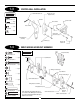
5-1 TAIL OUTPUT SHAFT/PULLEY ASSEMBLY Complete Assembly ........1 pc Spring Pin Tail Output Shaft Spring Pin Hammer Short Distance Note correct direction of Tail Output Shaft during assembly. 5-2 Long Distance Edge of Work Bench Tail Case Pulley TAIL GEAR CASE ASSEMBLY 3x12mm Self Tapping Screw 3x12mm Self Tapping Screw Tail Gear Case (L/R) Tail Output Shaft Bearing Tail Output Shaft Bearing 2.6x12mm Socket Head Bolt (4 pc) Tail Drive Belt Use Threadlock Tail Boom ........
5-3 TAIL CENTER HUB ASSEMBLY * Be certain to apply Locktite to the two 3x3mm set screws and attach securely to the tail output shaft so the set screws engage into the tail output shaft hole. Failure to secure this assembly properly can result in tail rotor failure during flight. 3x3mm Set Screw (2pc) * Tail Center Hub Tail Blade Holder Bearing (4pc) Tail Output Shaft Hole Tail Slide Ring Assembly * Use Threadlock 3mm Lock Nut (2 pc) .......2 pc 3x3mm Set Screw ........2 pc 3mm Lock Nut ........
5-5 TAIL PITCH CONTROL LEVER INSTALLATION ........1 pc 2x8 Flat Head Screw .......1 pc 2x20mm Socket Head Bolt ........1 pc 2mm Flat Washer ........1 pc Steel Joint Ball ........1 pc Tail Lever Bushing Snap Onto Ball Tail Pitch Control Lever 2mm Flat Washer Tail Lever Bushing 2x20mm Socket Head Bolt 5-6 Steel Joint Ball 2x8mm Flat Head Screw TAIL FIN ATTACHMENT Vertical Fin 3x10mm Socket Head Bolt ........2 pc 3x8mm Socket Head Bolt ........1 pc 3x10mm Socket Head Bolt ........
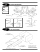
5-7 TAIL BOOM CARRIER INSTALLATION 3mm Lock Nut Tail Boom Carrier (L&R) ........4 pc 3x15mm Socket Head Bolt 3mm Lock Nut ........2 pc 3x40mm Socket Head Bolt ........6 pc 3mm Lock Nut * Do not fully tighten at this time. These bolts will be secured in Step 5-10. *3x15mm Socket Head Bolt *3x40mm Socket Head Bolt 5-8 TAIL BOOM ASSEMBLY INSTALLATION Slide the Tail Boom through the Tail Boom Carrier and engage the Tail Drive Belt over the Front Pulley.
5-9 TAIL BOOM BRACE ASSEMBLY Tail Brace Connector ........1 pc 2.6x12mm Socket Head Bolt 2.6x15mm Socket Head Bolt ......1 pc 2.6x15mm Socket Head Bolt 2.6x12mm Socket Head Bolt Tail Brace Tube Tail Brace T End 5-10 TAIL BOOM BRACE INSTALLATION ........2 pc 3x8mm Socket Head Bolt 3mm Lock Nut ........1 pc 3x10mm Socket Head Bolt ........1 pc 3mm Lock Nut 3x10mm Socket Head Bolt 3x8mm Socket Head Bolt (2 pc) Secure the four Socket Head Bolts left loose from Step 5-6.
6-1 UPPER SERVO TRAY INSTALLATION 3x8mm Socket Head Bolt (4 pc) Upper Servo Tray ......4 pc 3x8mm Socket Head Bolt RADIO INSTALLATION SUGGESTIONS Be sure to install four rubber servo grommets and eyelets to each servo prior to installation. When securing the servos to the helicopter, be sure not to overtighten the mounting screws. It is suggested that both the receiver and gyro amplifier be isolated from vibration by wrapping them in foam, then securing them to the model using double-sided servo tape.
6-2 SERVO/SWITCH HARNESS INSTALLATION Inner Holes are for JR Servos 2.6x12mm Self Tapping Screw 2.6mm Flat Washer ......20 pc 2.6x12mm Self Tapping Screw ......20 pc 2.6mm Flat Washer (4 Per Servo) * Note correct Servo Output Shaft orientation dring installation. Outer Holes are for Futaba Servos 2.6mm Flat Washer 2.
6-3 TAIL CONTROL ROD ASSEMBLY Thread Link 8mm onto Control Rod Tail Control Rod Bushings (5 pc) Universal Link (2 pc) ......5 pc Tail Control Rod Bushing Tail Control Rod Universal Link ......2 pc 6-4 Thread Link 8mm onto Control Rod TAIL CONTROL ROD INSTALLATION Tail Contol Rod Guide (4 pc) Tail Control Rod Clip located on Main Fram Note: 2x8mm Self Tapping Screw ......4 pc 2x8mm Self Tapping Screw Insert the Tail Control Rod Assembly into the four guides through the inner holes.
6-5 GYRO/RECEIVER/BATTERY INSTALLATION Caution: Be certain when installing the Gyro to the Gyro Mounting Plate that it does not come in contact with the frame of the helicopter, and that the surfaces are free from oil, residue, etc. Clean if neccessary to insure proper adhesion. Note: Gyro Nylon Wire Ties, Double Sided Servo Tape, and Spiral Tubing are not included in this kit. Spiral Tubing (Available at local auto supply store) * Wrap with foam or sponge rubber individually before installation.
RADIO SYSTEM PREPARATION The following preparations are suggested for use with JR radio systems. However, these procedures are applicable to most other brand radio systems. These suggested adjustments are necessary to insure correct installation and attachment of the control linkages and servo horns. TRANSMITTER PREPARATION 1. 2. 3. Set all trim levers, trim knobs and switches to the neutral or zero positions. Turn the transmitter power switch to the “on” position.
7-1 AILERON LINKAGES A Special Note To Beginners: It is suggested that the maximum travel limits for aileron, elevator, pitch and rudder controls be reduced to 70%. Note: Attach the steel joint ball to the correct hole as shown below: ......... 1 pc 2x8mm Flat Head Screw Servo Horn ..........1 pc 2x8mm Flat Head Screw Steel Joint Ball Steel Joint Ball .........1 pc 2mm Hex Nut 2mm Hex Nut Make sure the Aileron Trim is in the center position before attaching the Servo Arm to the Servo. 2.
7-3 Note: COLLECTIVE LINKAGE INSTALLATION Make certain that the Collective Servo is in the neutral or hover position before securing the Servo Horn to the Servo. Servo Reversing Directions JR Reverse Futaba Reverse 90° 2x8mm Flat Head Screw Steel Joint Ball Servo Horn 2mm Hex Nut 2.3x35mm All Threaded Rod 20mm ..........1 pc Servo Horn Hole Selection Use This Hole ..........1 pc Steel Joint Ball 10.5mm 2x8mm Flat Head Screw 21mm ..........
7-5 THROTTLE LINKAGE INSTALLATION (ALL) 2x8mm Flat Head Screw ..........1 pc 2x8mm Flat Head Screw Servo Horn Steel Joint Ball ..........1 pc Steel Joint Ball ..........1 pc 2mm Hex Nut 2mm Hex Nut Servo Reversing Directions JR Reverse Futaba Reverse Note: Low Throttle High Throttle Make sure that the Throttle Trim is in the low position before attaching the Servo Horn. SERVO HORN SELECTION/LINKAGE ADJUSTMENTS JR System/Webra .33 Engine or Thunder Tiger Pro .46 Heli Engine JR System/O.S. .
8-1 BODY ASSEMBLY/CANOPY ATTACHMENT Rubber Grommets (4 pc) Body Note: It will be necessary to trim away the unwanted plastic off the canopy and side window areas using an X-Acto knife. ..........5 pc 2.3x8mm Self Tapping Screw 8-2 *Canopy (Trim prior to attachment) 2.3x8mm Self Tapping Screw (5 pc) Drill four 15/64" holes and insert Rubber Grommets as shown. *After trimming, attach the canopy to the body temporarily with tape.
8-3 MAIN ROTOR BLADE BALANCING Main Rotor Blades Step 1 Step 2 Drinking Glass (2 pc) Spanwise C.G. Balancing Place each rotor blade on a sharp edge of a table as shown and adjust so each rotor blade “teeters” on the edge of the table. If the blades are correctly balanced, they should be at an equal distance to the edge of the table. If they are not, apply tape to the center of the light or short blade until equal distance can be achieved.
FINAL SERVO ADJUSTMENT AND RADIO SET UP Now that the radio system is completely installed into the helicopter, it is necessary to check and adjust the following: 1. Servo Direction (Servo Reversing) Check to insure that all servos have been set to the correct direction as shown in the Control Linkage Installation Section (Steps 7-1 to 7-5). 2. Dual Rates It is suggested that for initial flights, the dual rate function values be set as follows: 0 Position (low rate) 60% 1 Position (high rate) 100% A.
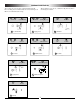
B. Throttle Curve Settings Below are several examples of possible throttle curves during various flight conditions. Since throttle curves can vary greatly due to engine and muffler combinations, it will be necessary to fine tune and adjust these values during test flights to achieve a constant main rotor RPM.
XF622 DATA SHEET #1 ERGO .32/.46 (INITIAL SET-UP) MDL 1 2 TYP AC HE D/R SW GEAR FACTORY PRE-SET *REVERSE SW SW FACTORY PRE-SET THR AIL ELE RUD GER PITCH NORM REV NORM REV NORM REV NORM REV NORM REV NORM REV SUB-TRIM Adjust so that no trim is required TRAVEL ADJUST Adjust for Full Power +80% +80% +100% + % +150% (TRV ADJ.
XP642 DATA SHEET #1 ERGO .32/.46 (INITIAL SET-UP) * Note: Before flying, confirm that all controls function in their proper direction. Modulation S-PCM • Z-PCM • PPM (FM) Model Number 1 Model Name E32 CHANNEL THR (1) AIL (2) ELE (3) RUD (4) GER (5) PITCH (6) NORM • REV NORM • REV NORM • REV NORM • REV NORM • REV NORM • REV * REVERSE SW SUB-TRIM Adjust so that no trim is required Adjust for full power + Adjust for engine off - TRAVEL ADJUST (TRV ADJ.
XP642 DATA SHEET #2 ERGO .32/.46 (INITIAL SET-UP WITH 3D PITCH/THROTTLE CURVE) Modulation S-PCM • Z-PCM • PPM (FM) Model Number Model Name * Note: Before flying, confirm that all controls function in their proper direction. 2 E46 CHANNEL THR (1) AIL (2) ELE (3) RUD (4) GER (5) PITCH (6) NORM • REV NORM • REV NORM • REV NORM • REV NORM • REV NORM • REV * REVERSE SW SUB-TRIM Adjust so that no trim is required Adjust for full power + Adjust for engine off - TRAVEL ADJUST (TRV ADJ.
XP-783 DATA SHEET ERGO .32/.46 (INITIAL SET-UP) MODEL NO. AILE ELEV RUDD D/R 90 % 90% 70 % D/R EXP 25% 25% 30% EXP D/R 100% 100% 100% AUTO D/R (POS.1) 0 STUNT TRIM * REVERSE SW ADJUST % MODULATION S-PCM • Z-PCM • PPM INH • ACT ST-2 INH • ACT D/R • R HOLD 40% Adjust as necessary during flight INH • ACT THRO AILE ELEV RUDD GEAR PITCH AUX2 NORM REV NORM REV NORM REV NORM REV NORM REV NORM REV NORM REV SUB-TRIM TRAVEL % ERGO .32/.
MODEL NO. (84) _____________________________________ PCM10SX DATA SHEET ERGO .32/.46 (INITIAL SET-UP) MODEL NAME (81) ERGO .32/.
PCM10SX DATA SHEET ERGO .32/.46 (INITIAL SET-UP) CONTINUED EXP OFF • ON N THRO CURVE (18) TH,TRIM=SLOW HOV.T=CENTER OFF • ON OFF • ON OFF • ON OFF • ON 1 *2 3 4 OFF • ON N OFF • 1 PITCH ON OFF CURVE • * 2 ON (68) OFF • 3 P,TRIM=CENTER ON HOV.P=CENTER OFF • 4 ON OFF HOLD • ON OFF INVT • ON L IN 0 OUT 0 —— HOV.
FINAL PRE-FLIGHT CHECK Once all assemblies have been completed, please review the following suggestions before attempting initial flights. • • • Review the instruction book and confirm that all assembly steps have been completed thoroughly. Check to verify that the tail rotor assembly rotates in the correct direction (see the diagram below). Check to insure that all servos are operating smoothly and in the correct direction.
GENERAL MAINTENANCE Engine After each day of flying, fully drain the fuel tank. Then, start the engine and let it idle until the engine and the fuel line are completely burned off. It is also suggested that an after-run oil be used to prevent premature engine corrosion. Check to insure that all universal links fit freely but securely to the control balls. If there is excessive play noted, replace the universal link in question.
ROTOR HEAD/SWASHPLATE/WASHOUT ASSEMBLY 960062 980049 960068 960070 960071 980023 983003 983004 960064 970029 981004 960066 960063 960067 960069 960065 970030 970002 970013 960013 970011 960060 960012 960059 960014 970010 970006 960081 970004 970001 52 960075
ROTOR HEAD/SWASHPLATE/WASHOUT ASSEMBLY PARTS LIST PART # DESCRIPTION QUANTITY 960012 960013 960014 Washout Assembly Washout Base Swashplate Assembly 1 1 1 960059 960060 960061 960062 960063 Flybar Paddles Flybar Rotor Head Assembly Head Button Main Blade Holder 2 2 1 1 2 960064 960065 Main Rotor Body Mixing Arms 1 2 960066 Main Rotor Hub 1 960067 Seesaw Shaft 1 960068 960069 960070 960071 960075 Blade Spindle Shaft Flybar Control Arm Blade Damper Rubber Blade Holder Spacer A Linkage Set A
START SHAFT/CLUTCH/ENGINE ASSEMBLY 960007 96005 960016 960018 960003 970009 960004 960011 960018 960006 960019 960078 (optional) 960008 960039 960040 950032 54
START SHAFT/CLUTCH/ENGINE ASSEMBLY PARTS LIST PART # DESCRIPTION QUANTITY 960003 Clutch Assembly 1 960004 Clutch Bell Assembly 1 960005 960006 960007 960008 Starter Hex Adaptor Start Shaft Assembly Front Tail Belt Pulley Engine Mount .32-.36 1 1 1 1 960039 960011 960016 960018 960019 960040 970009 Engine Mount .46 Cooling Fan Blades .32-.36 Start Shaft Bearing Block Tail Drive Pinion Bearing Block Fan Hub .32-.36 Aluminum Fan Assembly .46 Tail Drive Pinion w/Shaft 1 1 1 1 1 1 1 960078 .32-.
CYCLIC MIXING ARMS/ELEVATOR/AILERON CONTROL ARMS 960024 970002 980049 960025 970015 960023 970003 970003 970019 970017 970018 970012 970014 980049 960015 970004 960076 960020 980049 970016 960022 970016 56 960022 960021
CYCLIC MIXING ARMS/ELEVATOR/AILERON CONTROL ARMS PARTS LIST PART # DESCRIPTION QUANTITY 960015 Roll Bellcrank 1 960020 Elevator Arm: Front 1 960021 Elevator Arm: Rear 1 960022 960023 960024 Swashplate A Arm Mixing Base Arm: Roll Mixing Base Arm: Collective 2 1 1 960025 Mixing Lever: Cyclic 3 960076 Linkage Set B 1 970002 970003 970004 970012 970014 970015 970016 970017 970018 970019 980049 Steel Joint Ball w/2x10mm Screw Mixing Base Nut Universal Ball Link Washout Arm Bushing Mixing Le
UPPER MAIN FRAME/RADIO TRAY/BODY SET 960072 982002 982001 960031 970004 970005 960077 960002 970022 970008 960035 960009 960001 970005 960017 970020 960029 970024 58
UPPER MAIN FRAME/RADIO TRAY/BODY SET PARTS LIST PART # DESCRIPTION QUANTITY 960001 960002 960009 960017 960029 960031 Autorotation Assembly Main Drive Gear 88T Main Rotor Shaft Main Shaft Bearing Block Upper Main Frame Servo Mounting Plates 1 1 1 1 2 4 960035 Upper Servo Tray 1 960072 960077 Rubber Grommet Linkage Set C 4 1 970004 970005 970008 970020 970022 Universal Ball Links Autorotation Shaft Hub Sleeve Main Shaft Collar Main Frame Standoff: 32mm Body Mounting Standoff 10 1 1 2 4 970024
LOWER MAIN FRAME/LANDING GEAR/FUEL TANK 960030 960026 960027 960030 970022 960010 970021 960027 960028 970022 960117 960038 960039 960037 980013 960040 980036 980015 960036 960033 960038 960034 970023 60
LOWER MAIN FRAME/LANDING GEAR/FUEL TANK PARTS LIST PART # DESCRIPTION QUANTITY 960010 960026 960027 960028 960030 960032 Cooling Fan Shroud Gyro Mounting Plate Lower Frame Angles Front Radio Bed Lower Main Frame Landing Gear Set 1 1 2 1 2 1 960033 960034 960036 960037 Landing Struts Landing Skids Antenna Tube Fuel Tank Set 2 2 3 1 960038 970021 970022 Tank Mounting Rubber Main Frame Standoff: 60mm Body Mounting Standoff 2 2 4 970023 970025 960117 Landing Skid Caps Switch Damper Rubber Landing G
TAIL BOOM/TAIL BRACE/TAIL BOOM CARRIER 960048 960047 983002 960045 960046 960044 960046 983001 960042 960041 960043 62
TAIL BOOM/TAIL BRACE/TAIL BOOM CARRIER PARTS LIST PART # DESCRIPTION QUANTITY 960041 Tail Brace Set 1 960042 960043 Tail Brace Tube Tail Brace T End 1 1 960044 960045 Tail Brace Connector Tail Fin Set 1 1 960046 Horizontal Tail Fin/Brace Clamp 1 960047 Tail Boom Carrier 1 960048 Tail Rod Guide Set 4 983001 983002 Tail Boom Tail Control Rod 1 1 COMMENTS /ADDITIONAL CONTENTS 1 - Tail Brace Tube 1 - Tail Brace Connector 1 - Tail Brace T End 1 - 2.6x12mm Socket Head Bolt 1 - 2.
TAIL CASE/TAIL BLADE HOLDERS/TAIL PITCH PLATE 960051 960056 970026 960052 960058 970028 960050 970222 960057 960053 970027 960049 960055 981003 981003 960054 980007 970001 960053 .32-.36 AND .46 ASSEMBLY INSTRUCTIONS 960074 ERGO SPECIFICATIONS Overall Length Overall Height Main Rotor Diameter 46.5" 16.38" 48.5" (32-36) 50" (46 3D) Tail Rotor Diameter Gear Ratio Gross Weight 9.17" 9.78:1:5.18 6.75-7.0 lbs.
TAIL CASE/TAIL BLADE HOLDERS/TAIL PITCH PLATE PARTS LIST PART # DESCRIPTION QUANTITY 960045 Tail Fin Set 1 960049 960050 960051 960052 Tail Drive Belt Tail Slide Ring Assembly Tail Rotor Blades Tail Blade Holder Set 1 1 2 2 960053 Tail Case Set (L&R) 1 960054 Tail Pitch Control Lever 1 960055 960056 960057 960058 960074 970001 970222 970027 970028 981003 Tail Case Pulley Tail Pitch Link Tail Pitch Plate Tail Slide Ring Ergo .32/.
Heli Division Revised 3/4/97