
User's Manual
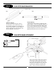


Now that the radio system is completely installed into the helicopter, it is
necessary to check and adjust the following:
1. Servo Direction (Servo Reversing)
Check to insure that all servos have been set to the correct direction as
shown in the Control Linkage Installation Section (Steps 7-1 to 7-5).
2. Dual Rates
It is suggested that for initial flights, the dual rate function values be
set as follows:
0 Position (low rate) 60%
1 Position (high rate) 100%
3. Exponential Settings
It is suggested that the exponential rate settings remain in the 0 value
position until the initial test flights. After initial flights, adjust the
exponential values to achieve the desired control feel.
4. Sub-Trim Settings
It is suggested that the correct neutral settings be achieved without the
use of the sub-trim feature. If sub-trim is used for final flight
adjustments, it is not suggested that the sub-trim values exceed 10. If
the sub-trim values are greater, readjust the control linkages and reset
the sub-trims to 0.
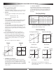
5. Travel Adjustment
The travel adjustment feature allows the control surface to be
adjusted to achieve maximum travel, or surface deflection. When using
this feature, it is extremely important that the high/low, up/down
values for each channel be set at an equal value or a differential
movement will occur (Diagram B). It is especially important that the
throttle and collective pitch travel limits are set to an equal value
(Diagram A).
Please refer to the diagrams below for clarification.
6. Pitch/Throttle Curve Adjustment
It is very important that the throttle and pitch curves are adjusted
properly to achieve the best performance from your helicopter. When
properly adjusted, the main rotor head RPM should remain consistent
throughout all maneuvers and throttle stick positions. A constant RPM
will also help to improve the effectiveness and accuracy of the tail rotor
and gyro systems.
A. Pitch Curve Adjustment
Using a pitch gauge (optional) set the low, mid and high stick pitch
settings as shown in the diagram below. Use the travel adjust feature
to set the maximum high and low pitch required for all flight modes.
This pitch travel can then be reduced by altering the pitch curves as
shown below.
Note: * To achieve this pitch range settings with the Ergo, it will be
necessary to use the optional “B” style double link set (#960081).
(This item is included with the Ergo .46 kit.)
Note: When using the “B” style double link set for 3D flight, the
maximum pitch range is altered to +10¯ – ¯10, reducing the + pitch
range for autorotations.
42
FINAL SERVO ADJUSTMENT AND RADIO SET UP
Correct
50
50
50
100
+10°
0°
-10°
-10°
+13°
5°
-5°
13°
8.5°
-5°
13°
10°
5°
-5°
-5°
-2°
A
Incorrect
Hovering (Linear Curve)
Flight Mode
N
Flight Mode
1
Flight Mode
2 (optional)
Flight Mode
H
Stick Position
Stick Position
Low
Half High Low
Half
High
Stick Position
Low
Half
High
Stick Position
Low
Half
High
Stunt & Aerobatic Flight
Autorotation
3D Flight (Ergo 46)
B
50
100
Straight & Linear Servo Travel
Non-Linear Servo Travel
Flight Application Low Pitch Hovering Pitch High Pitch
Mode (Low Stick) (Half Stick) (High Stick)
N Hovering -2° 5° 10°
I Stunt & Aerobatic Flight -5° 5° 8.5°
*2 3D Flight (Ergo 46) -10° 0° 10°
H Auto-Rotation -5° 5° 13°
100
100
Pitch Range Settings
Pitch Curve Settings
Pitch Range Pitch Range
Pitch Range Pitch Range