User's Guide Tablet Charging Wall Mount 12 ENGLISH For the latest User Installation Guide please visit: www.ergotron.com User's Guide - English Guía del usuario - Español Manuel de l’utilisateur - Français Gebruikersgids - Deutsch Benutzerhandbuch - Nederlands Guida per l’utente - Italiano Användarhandbok - svenska ユーザーガイド : 日本語 用户指南 : 汉语 888-61-070-G-02 rev.
Hazard Symbols Review Symbol These symbols alert users of a safety condition that demands attention. All users should be able to recognize and understand the significance of the following Safety Hazards if encountered on the product or within the documentation.
Components A B C D 1x 1x 1 5x 1x 1x 4x 2 1/4”-20 x 2” 1x 3 5x 4x M6 x 70mm 5/32” ENGLISH Tools Needed Stud Finder 2 1 10mm WOOD STUD HOLLOW WALL Ø 3/16" (5 mm) Ø 1/2" (13 mm) CONCRETE Ø 3/8" (10 mm) 888-61-070-G-02 rev.
1 MOUNTING CONSIDERATIONS Space Requirements: When mounting to wood stud, at least one screw in the upper mounting bracket must be installed in a stud (preferably the center hole). 35.3" (900 mm) 6" (152 mm) 7" 11.8" 6.5” (178 mm) (300 mm) (168 mm) 4” (102 mm) 6" (151 mm) 3" (74 mm) Mounting Holes 35.6" 32.75" (905 mm) ENGLISH (831 mm) Individual tablet or chromebook weight: Individual dimensions (including cover): < 11.
WOOD STUD HOLLOW WALL a First Choose a Hole Option: The stud can be located at one of five mounting holes on the top bracket. While the first option (center hole of bracket) is recommended, you should consult with a construction professional to confirm which method is best suited for your particular situation. After you decide on a Hole Option, follow attachment instructions on the following page.
WOOD STUD HOLLOW WALL b Find stud and draw a mark. c Put a mark on the stud 62”-68” (158-173 cm) from floor. ENGLISH 62”-68” (158-173 cm) d Place template on wall lining up the chosen hole with the stud and the mark 62”-68” (158-173 cm) from floor. e Secure template to wall. 62”-68” (158-173 cm) 7 888-61-070-G-02 rev.
WOOD STUD HOLLOW WALL f 1. Drill the three holes for the top bracket that correspond with the hole option determined on previous page. 2. Drill the bottom two holes. NOTE: Use the Ø 3/16” (5 mm) drill bit when drilling directly into the wood stud. Use the Ø 1/2” (13 mm) drill bit when drilling into the hollow wall for the anchors. Use hollow wall anchors where ever a screw does not get inserted directly into the wood stud.
CONCRETE a b Put a mark on the stud 62”-68” (158-173 cm) from floor. Attach template to the wall lining up the chosen mounting holes with the mark 62”-68” (158-173 cm) from floor. 60”-66" (1524-1676 mm) 60”-66" (1524-1676 mm) c d Drll the top 3 holes, then the bottom two holes. ENGLISH Ø 3/8" (10 mm) 3-1/8" (80 mm) WARNING: Mounting holes must be at least 3-1/8” (80mm) deep and must be located within solid concrete, not mortar or covering material.
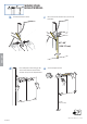
3 Hang unit onto top bracket. Warning: 2 people are required to lift this product. 4 a. Remove two screws on left side. Save screws for reattaching cover. b. Unlock door and turn wing knob 90° clockwise. a b ENGLISH 5 a. Open door and remove these 3 screws. Save screws for reattaching cover. b. Remove left cover a b 888-61-070-G-02 rev.
6 a. Secure unit to wall by inserting screw through back wall and into bottom right wall anchor. b. Close door, then insert screw through back wall and into bottom left wall anchor. WOOD STUD HOLLOW WALL CONCRETE 5x 5/32” 2x 1/4”-20 x 2” M6 x 70mm 10mm a b b ENGLISH a 888-61-070-G-02 rev.
7 a. Plug in all the tablet power cables into the outlets inside. b. Route cables through the access holes. c. Open door an pull cables through the access holes. a b ENGLISH c 888-61-070-G-02 rev.
Pull out tablet tray and insert tablet. NOTE: Tablet should be positioned so power plug is at top or left side. ENGLISH 8 9 a. Pull cable clip off of tablet slot and route cable through clip, then reattach cable clip. NOTE: Leave enough slack in cable to plug into tablet. b. Plug tablet cables into tablets. NOTE: When tablet is removed, store unconnected cable in the appropriate tablet slot. a b 888-61-070-G-02 rev.
10 Tie up excess cable with velcro cable ties. NOTE: Keep cables away from power system components that might get hot during operation. ENGLISH 11 a. Attach left cover with 2 screws saved from removal of cover. b. Open door and attach 3 inside screws saved from removal of left cover a b 888-61-070-G-02 rev.
12 ENGLISH a 13 a. Close door. b. Lock door by rotating wing knob 90° counterclockwise. b Plug power cable into bottom access and then into wall outlet to start charging. 888-61-070-G-02 rev.
Tablet Charging To begin charging the tablets, plug in the power cord. The power cord is used to turn the power on and off. Charging occurs whenever the power cord is connected to an outlet. LED NOTE: The power cord acts as the connect/disconnect device switching power off and on. The socket outlet shall be installed near the equipment and shall be easily accessible. Power Indicator – Communicates charge status with the following signals: Light Description Off No power to the module.
Cleaning and Maintenance Equipment Electric Safety There are specific risks associated with the use of equipment having power cables. You must be aware of, and avoid these risks when this product is located in close proximity to children. WARNING: Failure to observe the following Electrical Safety notices can result in fire or death by electric shock. Electrical cables can be hazardous. Misuse can result in fire or death by electrical shock.
Service and Warranty For local customer care phone numbers visit: http://contact.ergotron.com NOTE: When contacting customer service, reference the serial number. www.ergotron.com MADE IN CN 12-345-678 1234567-1234 ENGLISH 888-61-070-G-02 rev.