
User Manual


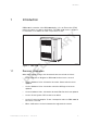

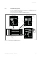
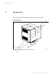
Table Of Contents
- toc
- 1 Introduction
- 2 Product Overview
- 3 Dimensions
- Size and Weight
- Surface and Colour
- 4 Space Requirements
- Footprint
- 5 Environment
- 6 Hardware Units
- 7 Interfaces
- 7.1 External Connections
- Connections on DF
- Overvoltage Protection Modules in the RBS 2106i and RBS 2106 V3
- Overvoltage Arrestors for External Alarms in the RBS 2106
- Antenna Connections
- Other External Connections
- External Connections to TM
- Transport Network to TM
- 7.2 Test Interface
- 7.3 Operator Interface
- Indicators
- Buttons
- 8 Power System
- 8.1 Power Supply
- AC Mains Supply Voltage
- External Earth Fault Circuit Breakers
- Mains Fuses
- 8.2 Battery Backup
- Internal Battery Backup
- External Battery Backup
- 8.3 Output Power to TM
- 8.4 Power Consumption
- 9 Transmission
- Optional Transmission Equipment
- 10 External Alarms
- 11 Standards, Regulations and Dependability

PRELIMINARY
Product Overview
• Internal battery backup
• RBS synchronization through the Global Positioning System (GPS)
• Power supply system: can be connected to 200 – 250 V AC mains supplies
• Radio configurations supported on 800, 900, 1800, and 1900 MHz
• Receiver diversity
• Transmission Interface: the following transport network interface
alternatives exist:
T1 1,544 kbps, 100
, with PCM synchronization
E1 2,048 kbps, 75
, with PCM synchronization
E1 2,048 kbps, 120
, with PCM synchronization
2.2 Variants
The RBS 2106 is available in three variants:
• RBS 2106
• RBS 2106i
• RBS 2106 V3
The RBS can be equipped with variants of the following items, as selected
when ordering:
• Heat exchanger climate unit or combined climate unit
• Two standard colours
• AC service outlet according to local standards, or not
2.3 Optional Equipment
The equipment listed below is available but not necessary for basic operation:
• Auxiliary Distribution Module (ADM)
• Antenna-Sharing Unit (ASU)
• Base frame
• Battery backup
• Control Module for Tower-Mounted Amplifiers (TMA-CM)
3
129/1551-LZA 701 0001 Uen PF1 | 2010-10-08