
User Manual


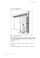

Table Of Contents
- toc
- 1 Introduction
- 2 Product Overview
- 3 Dimensions
- Weight
- Colour
- 4 Space Requirements
- Space above the RBS Cabinet
- Layout for RBS Cabinets
- Earthquake Requirements
- Footprint
- 5 Environment
- 6 Hardware Units
- 6.1 RBS 2206 Standard Hardware Units
- ACCU-01
- CDU
- CXU-10
- DCCU-01
- dTRU
- DXU-21
- FCU
- IDM-01
- PSU
- DC Filter-01
- 6.2 RBS 2206 V2 Standard Hardware Units
- ACCU-11
- CDU
- CXU-10
- DCCU-11
- DCCU-13
- dTRU
- DXU-23
- IDM-11
- PSU
- 6.3 Optional Hardware Units
- ASU-01
- Bias Injector
- BBS
- ddTMA
- DXX
- DF
- ESB
- HCU
- 19-inch Space for Optional Equipment
- OXU
- Splitter
- TMA-CM-01
- TMA-CM-02
- 7 Interfaces
- 8 Power System
- 9 Transmission
- Overvoltage Protection Modules
- Optional Transmission Equipment
- 10 External Alarms
- 11 Standards, Regulations and Dependability

Product Overview
0
E1 2048 kbps, 120
, with PCM synchronization
• Wide-range power input 120 – 250 V AC
2.2 Variants
Three versions of the RBS 2206 and RBS 2206 V2 cabinets are available:
•
0
48 to
0
60 V DC
• 120–250 V AC (50/60 Hz) and +24 V DC
• +24 V DC, without Power Supply Unit (PSU)
2.3 Optional Equipment
The equipment listed below is available, but is not necessary for basic
functionality.
• Antenna Sharing Unit (ASU)
• Splitter unit
• Battery backup, external only
• Bias injectors
• Distribution Frame (DF), externally mounted
• Dual-Duplex Tower-Mounted Amplifier (ddTMA), externally mounted
• Digital Cross-Connect (DXX), transmission equipment
• External Synchronization Bus (ESB)
• Hybrid Combiner Unit (HCU)
• Redundant PSU
• Tower-Mounted Amplifier Control Module (TMA-CM)
• Transmission Adapter (TA), 75–120
319/1551-LZA 701 0001 Uen PG1 | 2010-10-08