
User Manual

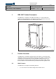
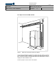
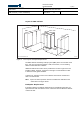

Table Of Contents
- toc
- tables
- Table 1 Weight
- Table 2 Color
- Table 3 Environmental Specifications
- Table 4 Compliance Boundary Dimensions for the General Public (G
- Table 5 Characteristics for a Typical Antenna (KRE 101 1916/1)
- Table 6 Maximum Power to Antenna for Various RBS 2207 Configurat
- Table 7 External Connections
- Table 8 Power Supply Voltage Alternatives
- Table 9 AC Mains Power Requirements
- Table 10 Mains Fuses Recommendation
- Table 11 DC Power Requirements
- Table 12 +24 V DC Fuse Recommendation
- Table 13 DC Supply Voltage Requirements
- Table 14 −48 to −60 V DC Fuse Recommendation
- Table 15 Power Consumption

Ericsson Internal
DESCRIPTION 4 ( 24 )
/ XSNJOER 174/1551-LZA 701 0001 Uen
EAB/ FJG/YP ( Louise Cederlund) 2007-06-12 A
Prepared (also subject responsible if other) No.
Approved Checked Date Rev Reference
• Discontinuous transmission/reception
• Duplex filters
• Dynamic power regulation
• Encryption/ciphering
• EDGE
• Expansion by Transceiver Group (TG) synchronization
• External alarms
• Frequency hopping
• Global positioning system (GPS) synchronization
• Radio configurations supported on 800, 900, 1800 and 1900 MHz
• Receiver diversity
• Transmission Interface: The following transport network interface
alternatives exist:
T1 1.5 Mbit/s, 100 , with internal synchronization
E1 2 Mbit/s, 75 , with PCM synchronization
E1 2 Mbit/s, 120 , with PCM synchronization
• Wide range power input 120–250 V AC
• Wide range power input
48 to 60 V DC
2.2 Variants
There are three RBS 2207 cabinet versions:
•
48 to 60 V DC
• 120–250 V AC, 50 to 60 Hz, +24 V DC, with optional battery backup
• +24 V DC (without PSUs)
2.3 Optional Equipment
The equipment listed below is available, but is not necessary for basic
functionality.
• Battery backup (in a separate cabinet)
• Bias injectors