
User Manual

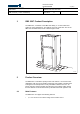
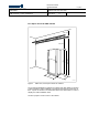
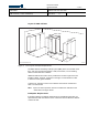
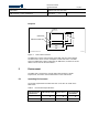

Table Of Contents
- toc
- tables
- Table 1 Weight
- Table 2 Color
- Table 3 Environmental Specifications
- Table 4 Compliance Boundary Dimensions for the General Public (G
- Table 5 Characteristics for a Typical Antenna (KRE 101 1916/1)
- Table 6 Maximum Power to Antenna for Various RBS 2207 Configurat
- Table 7 External Connections
- Table 8 Power Supply Voltage Alternatives
- Table 9 AC Mains Power Requirements
- Table 10 Mains Fuses Recommendation
- Table 11 DC Power Requirements
- Table 12 +24 V DC Fuse Recommendation
- Table 13 DC Supply Voltage Requirements
- Table 14 −48 to −60 V DC Fuse Recommendation
- Table 15 Power Consumption

Ericsson Internal
DESCRIPTION 8 ( 24 )
/ XSNJOER 174/1551-LZA 701 0001 Uen
EAB/ FJG/YP ( Louise Cederlund) 2007-06-12 A
Prepared (also subject responsible if other) No.
Approved Checked Date Rev Reference
Footprint
Unit of measurement: mm
P010951A
(RBS 2202)
FRONT
99
400
598
220
45
320
400
o 20x75
RBS 2206 / RBS 2207
Figure 3 Hole Pattern Overview
The RBS 2207 has the same footprint as the RBS 2202 and 2206 cabinets.
The base frame can be used as a template to mark new holes. If an RBS
2202 or an RBS 2206 is being replaced by an RBS 2207, the holes for the old
cabinet can be used for the new cabinet.
5 Environment
The RBS 2207 is designed to operate within limits stated for climatic
requirements, and also to have a limited effect on the environment.
5.1 Operating Environment
The climatic requirements the RBS 2207 has on the site are shown in the
table below.
Table 3 Environmental Specifications
Environmental
Parameters
Normal Operation
(1)
Safe Functio
n
Non-destructiv
e Conditions
(2)
Temperature
+5 to +40 C
0 to +45 C
-10 to +55 C
Relative Humidity
5–85% 5–90% 5–90%