LBI-39076 Mobile Communications EDACS Enhanced Local Interconnect (ELI) System Manual
LBI-39076 CONTENTS TABLE OF CONTENTS Page: LIST OF FIGURES AND TABLES......................................................................................................................... 4 REGULATORY COMPLIANCE............................................................................................................................. 5 SPECIFICATIONS...................................................................................................................................................
CONTENTS LBI-39076 TABLE OF CONTENTS (Cont.) OPERATION ........................................................................................................................................................... GTI Units .......................................................................................................................................................... Indicators............................................................................................................................
LBI-39076 FIGURES AND TABLES LIST OF FIGURES AND TABLES Page: Figure 1 - Typical Enhanced Local Interconnect System.......................................................................................... 7 Figure 2 - GTI Audio Paths ...................................................................................................................................... 8 Figure 3 - Location of Fastener Screws ...................................................................................................
REGULATORY COMPLIANCE LBI-39076 REGULATORY COMPLIANCE FEDERAL COMMUNICATIONS COMMISSION (FCC) REGULATIONS 1. This Telephone Interconnect, before its connection to a Telephone Central Office, must be reported to the "CENTRALIZED OPERATIONS GROUP" of the local area Telephone Company (not the business office) by the user, installer, or Installation Supervisor to ensure a smooth installation. The following two Central Office telephone connection configurations are possible: a.
LBI-39076 SPECIFICATIONS SPECIFICATIONS Dimensions: Master GTI ...........................................................1.75" H x 19.00" W x 12.00" D GTI ................................................................1.75" H x 19.00" W x 12.00" D IAM ................................................................1.75" H x 19.00" W x 7.00" D Environmental: Temperature Range...............................................0° to 70° C (32° to 158° F) Relative Humidity.......................................
INTRODUCTION / DESCRIPTION INTRODUCTION LBI-39076 DESCRIPTION This manual describes the installation, configuration, and operation of the Enhanced Local Interconnect (ELI) option. A companion manual, the Global Telephone Interconnect (GTI) Configurator user's manual (LBI39077), describes how to use the GTI Configurator software to configure the GTI units used in the ELI option.
LBI-39076 DESCRIPTION The Site Controller computer directs up to 16 levels of toll call restrictions, up to 15 rotary hunt sequences, 8 dequeuing priority levels, and inbound interconnect enable/disable assignments, for each ID number. It also accumulates interconnect call activity data for the System Manager.
DESCRIPTION One GTI converts the analog audio signal (from the radio connected to it) into a digital signal for placement onto the PCM/Data bus. Another GTI (or the same GTI) converts the digital signal from the PCM/Data bus back to an audio signal (for the telephone line connected to it). A similar route is taken by the signal from the telephone line to the radio. Each channel has its own time slot on PCM/Data bus so as not to interfere with any other channel.
LBI-39076 INSTALLATION SITE CONTROLLER SOFTWARE The 3rd step needed to install the ELI option is to check the version of the Site Controller computer’s Application Software. If it does not support the ELI option, you must obtain and install a newer version of Application Software that does. You must also replace the two existing Personality PROMs, whether the Application Software PROMs need replacing or not.
INSTALLATION CHANNEL ASSIGNMENTS The 4th step needed to install the ELI option, is to assign each GTI unit (including the Master GTI) to a repeater channel. Because the jumpers and DIP switches must be configured in the GTI units before they are mounted with their assigned repeater channel, there is an opportunity to get them mixed up and mounted with the wrong repeater channel.
LBI-39076 INSTALLATION is being used, special care must be taken to keep track of which GTI is configured for which type of circuit.
INSTALLATION LBI-39076 End-to-End, Loop Start End-to-End, Ground Start Figure 12 shows the GTI telephone interface circuit connected per Table 1 for End-to-End, Loop Start. Two wires are needed to connect to the telephone company side. Battery for the loop current is provided by the telephone company. Figure 13 shows the GTI telephone interface circuit connected per Table 1 for End-to-End, Ground Start. Two wires are needed to connect to the telephone company side.
LBI-39076 INSTALLATION 4-Wire E&M, Microwave 4-Wire E&M, Type I Figure 14 shows the GTI telephone interface circuit connected per Table 1 for 4-Wire E&M, Microwave. Eight wires are needed to connect to the telephone company side. Ground/battery for the M Lead and E Lead are provided by the microwave. Figure 15 shows the GTI telephone interface circuit connected per Table 1 for 4-Wire E&M, Type I. Six wires are needed to connect to the telephone company side.
INSTALLATION GTI DIP SWITCH SETTINGS The 7th step needed to install the ELI option, is to set the two 8-section DIP switches through openings in the right side of the GTI chassis. The orientation of the DIP switches is shown in Figure 16. FRONT 1 1 0 0 1 8 1 SW2 8 SW1 LBI-39076 DIP switch SW1, positions 1 through 6, are used to identify the assigned repeater channel number, also known as the telephone circuit number if one is to be connected to the GTI.
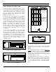
LBI-39076 INSTALLATION GTI INTERFACE CARD MOUNTING GTI INTERFACE CARD SOFTWARE The 8th step needed to install the ELI option, is to make a Master GTI from a standard GTI by adding a GTI Interface card. Each standard GTI contains two printed circuit boards, mounted as shown in Figure 17. A third board, the GTI Interface card, is added to one GTI unit at a site, making it the Master GTI.
INSTALLATION LBI-39076 GTI & IAM MOUNTING Telephone Line The 10th step needed to install the ELI option, is to mount the GTI units, Master GTI, and optional IAM (if supplied).
LBI-39076 INSTALLATION MASTR III Power Supply/Audio If the GTI unit is to be connected to a MASTR III repeater channel, connect a 19B803830P1 cable from the male 1x6-pin Molex connector on the back of the GTI (marked "POWER/AUDIO") to P4 on the MASTR III repeater T/R Shelf backplane, and to P801 on the repeater power supply, as shown in Figure 22. Note that the power supply end of the cable comes with pins attached to wires, but no connector shell.
INSTALLATION LBI-39076 PCM/Data Bus The PCM/Data bus is made up of a PCM/Data bus termination plug and one or more 12-pair shielded cables daisy-chained between each GTI, the Master GTI, and the optional IAM (if present). These cables have a stackable 24-pin connector on one end, and a standard 24-pin connector on the other. To install the data bus cables, connect the IAM unit (if present) first, then the Master GTI unit, and finally the standard GTI units (from the lowest channel to the highest channel).
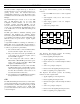
LBI-39076 INSTALLATION The IAM software is stored in U23 in the IAM. A sample label for U23 is shown in Figure 27. The actual version number of the software supplied may be different than that shown. Software Version # (C) ZETRON INC. IAM V1.2 2#56022 8/94 U23 601-0537/ IAM CONNECTIONS The 14th step needed to install the ELI option applies only if an IAM was supplied. All connections to the IAM are made to connectors on the rear panel, as shown in Figure 29.
INSTALLATION LBI-39076 Alarm Outputs The IAM provides three open-drain alarm outputs for the user to connect to an alarm system, if desired. These alarm outputs will go through indeterminate states during IAM power-up or reset. If the Active High output configuration is selected by setting DIP switch section 7 to the up position, all alarms will be active if the IAM loses power.
LBI-39076 CONFIGURATION CONFIGURATION OVERVIEW The user configurable parameters for the ELI option reside in two locations: the Site Controller computer’s database and the GTI units’ database. The configuration of these two databases is covered in this section. SITE CONTROLLER DATABASE The overall operation of the ELI option is controlled by the software in the Site Controller computer and the active configuration of the Site Controller computer’s database.
CONFIGURATION Radio Features Toll Call Restrictions - Defines which of 16 toll call restriction levels (from 0 to 15) is to be applied to this specific logical unit ID for interconnect calls - default is totally restricted (0). Logical Unit Definition (menu selection 11) Radio Parameters (panel 2:3) Interconnect Dedicated Line - Defines the line number (0 is a denial) to be dedicated to outgoing interconnect calls for this specific logical unit ID - default is 1.
LBI-39076 CONFIGURATION Pulse Dial - Defines if a line uses pulse dialing (as opposed to DTMF) - default is no (N) for all lines. Line Definition (menu selection 14) Line Parameters (pages 1 & 2) NOTE Note that the ELI system will ignore this parameter, so there is no point in changing it from its default value. However, the equivalent of this parameter must be set in the GTI user database.
CONFIGURATION Office PC Adapter COM Port D-Sub 25-Pin (M) Rx Data Tx Data LBI-39076 D-Sub 25-Pin (F) 3 DTR Signal Ground 2 20 7 RTS 4 CTS 5 GTI Unit D-Sub 9-Pin (M) D-Sub 9-Pin (F) 19D903985P72 Cable D-Sub RS-232 Port 9-Pin (M) D-Sub 9-Pin (F) 1 2 1 2 3 4 5 6 7 3 4 5 6 7 Rx Data DTR Gnd 8 9 8 9 RTS Tx Data CTS Figure 34 - Local GTI Connection for 25-Pin COM Port Remote Data Link A remote data link using data modems will be required if the GTI database must be configured from a lo
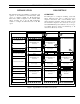
LBI-39076 OPERATION Hard Reset OPERATION GTI UNITS The location of the indicators and reset button on the front panel of each GTI unit (including the Master GTI) is shown in Figure 35. A hard reset returns each user-configurable parameter in each GTI unit’s user database back to the factory default value, but does not alter any voice prompts that have been recorded. A simultaneous hard reset of all GTI units can only be made through the GTI Configurator software.
OPERATION CDR Received Indicator The red LED labeled “CDR RECEIVED” should be lit momentarily each time a call record is received by the IAM. Alarm Indicator LBI-39076 CAUTION Retrieve all call detail records that you want to keep, using the Retrieve Call Detail Data operation in the GTI Configurator software, before clearing the RAM. When the RAM is cleared, all call detail records stored in RAM will be lost.
LBI-39076 OPERATION However, the IAM has alarm outputs that can be used to notify the user of a memory or bus problem that may result in the loss of billing data. For more information, see the subsequent section on alarm outputs. Status The status of the IAM can be read by using the GTI Configurator software. The GTI Configurator software will show if an IAM is present, the number of call records presently stored, the amount of memory free and memory used, any alarm conditions, etc.
OPERATION Telephone-Originated Call The sequence of steps for a telephone-originated call is as follows: DETECTING THE CALL 1. Somewhere in the telephone system, a user dials the telephone number of a subscriber line connected to a GTI unit. 2. The line-connected GTI detects the call by sensing the presence of a ringing voltage (or an E-lead signal), and sends a message to the Site Controller computer (Port 31) indicating that a call has been detected by this GTI unit. 3.
LBI-39076 OPERATION OBTAINING WORKING CHANNEL 20. If the call is allowed, the Site Controller computer checks to see if a working channel with a GTI is available. N. If no working channel with a GTI is currently available, the Site Controller computer queues the call. When the call comes out of queue, continue to next step. 21.
OPERATION A telephone interconnect number may be a complete or partial telephone number. (An example of a partial telephone number is an access code plus an area code.) When the telephone interconnect number is only a partial telephone number, the caller must supply the remaining digits of the telephone number as overdialed digits, after the telephone line has been connected and the trapped interconnect digits have been re-dialed on the telephone line.
LBI-39076 OPERATION 12. As the Site Controller computer receives the digits, it counts and stores each interconnect digit, and looks for the terminator digit. As soon as it counts 4 interconnect digits received or sees the terminator digit, it performs the toll call restrictions test for that radio ID, using wild-card digits if necessary.
TROUBLESHOOTING LBI-39076 TROUBLESHOOTING GTI DIP Switch Settings Incorrect - Check the DIP switch settings in the GTI unit. The hardware used in the ELI system is extremely reliable, making component failure the unlikely cause of most problems. The most common causes of problems are as follows: Cable Connected to Wrong Connector - Check interconnection wiring. Site Controller Computer Not Correctly Configured Check the configuration of the Site Controller database parameters using the System Manager.
LBI-39076 TROUBLESHOOTING Table 3 (Cont.) - Troubleshooting Symptoms SYMPTOM POSSIBLE CAUSE(S) CORRECTIVE ACTION All telephone-originated interconnect calls are unanswered on all lines. Site Controller computer not connected to the Master GTI. Check 19B803826P1 and P2 data cable connections. Jumpers and/or DIP switches in each GTI set incorrectly for line type. Check GTI jumper locations and DIP switch positions. GTI line type database configured incorrectly for each line.
TROUBLESHOOTING LBI-39076 Table 3 (Cont.) - Troubleshooting Symptoms SYMPTOM LIC Alarm with all RIC Alarms LIC Alarm with no RIC Alarms All RIC Alarms Adjacent RIC Alarms on equipped channel numbers Single RIC Alarm highest POSSIBLE CAUSE(S) CORRECTIVE ACTION Crossed 19B803826P1 and P2 data cables between Master GTI and Site Controller computer. Swap connections at either the Master GTI end or the Site Controller computer end. Bad GTI Interface card. Replace GTI Interface card.
LBI-39076 GLOSSARY GLOSSARY Channel-connected GTI ...............................................The Channel-connected GTI is the specific GTI unit connected to the EDACS repeater channel involved in the interconnect call being described. EDACS ........................................................................Enhanced Digital Access Communications System ELI ...............................................................................
PARTS LIST LBI-39076 GLOSSARY (CONT.) Site Controller Database ..............................................The Site Controller Database is the specific information about the site, such as equipment available at the site, validation tables by feature and priority for each Logical (individual) ID and Group ID, etc., maintained by the System Manager. If the site has no System Manager, the Site Controller Database uses the default values contained in the Site Controller computer's two Personality PROMs.
LBI-39076 INTERCONNECTION DIAGRAM 19C852327G1 Phone Module (EDACS Interface Panel) RJ-45 RJ-45 1 2 3 4 5 6 7 8 See Schematic Diagram for Details Phone (J1) RJ-45 RJ-45 1 13 2 14 3 15 4 16 5 17 6 18 7 19 8 20 9 21 10 22 11 23 12 24 100 Ohms 100 Ohms 100 Ohms 100 Ohms 100 Ohms 100 Ohms 100 Ohms 100 Ohms 100 Ohms 100 Ohms 100 Ohms 100 Ohms Left (J4) P4 RJ-11-6 Bit 1 Bit 2 Bit 3 PCM Data Bus Bit 4 Bit 5 Bit 6 Bit 7 Frame Sync Console Data bus Subscriber Data Bus Repeater Data Bus Bus Cable
SCHEMATIC DIAGRAM J14 25-Pair TO PUNCHBLOCK OR DAISYCHAIN J1 RJ-45 TO GTI UNIT 1 2 3 4 5 6 7 8 J2 RJ-45 TO GTI UNIT 1 2 3 4 5 6 7 8 LBI-39076 J3 RJ-45 TO GTI UNIT 1 2 3 4 5 6 7 8 J15 25-Pair 1 26 2 27 3 28 4 29 5 30 6 31 7 32 8 33 9 34 10 35 11 36 12 37 13 38 14 39 15 40 16 41 17 42 18 43 19 44 20 45 21 46 22 47 23 48 24 49 25 50 1 26 2 27 3 28 4 29 5 30 6 31 7 32 8 33 9 34 10 35 11 36 12 37 13 38 14 39 15 40 16 41 17 42 18 43 19 44 20 45 21 46 22 47 23 48 24 49 25 50 J4 RJ-45 1 2 3 4 5 6 7 8 TO
LBI-39076 INSTALLATION CHECKLIST INSTALLATION CHECKLIST Steps 1 through 15 parallel the main headings in the Installation section of this manual. For more details, see the heading that applies. Step 16 is covered in the Configuration section of this manual. Step 17 is covered in the User’s Guide for the GTI Configurator Software, LBI-39077. 1. RADIO SOFTWARE - If MDR full-duplex radios are to be used, check to make sure their software is G2 or higher. 2.