
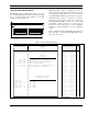
Specifications

L
BI-39076 INSTALLATION
14
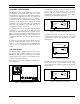
4-Wire E&M, Microwave
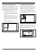
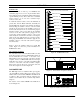
Figure 14 shows the GTI telephone interface circuit
connected per Table 1 for 4-Wire E&M, Microwave.
Eight wires are needed to connect to the telephone
company side. Ground/battery for the M Lead and E Lead
are provided by the microwave.
E Lead
M Lead
Trans-
former
former
Trans-
E-Lead Det.
4
5
3
6
2
1
7
8
To
Microwave
Rec Audio
Send Audio.
4-W Rec
4-W Send
4-W Send
4-W Rec
M-Lead Return
E-Lead Return
Figure 14 - 4-Wire E&M Microwave Circuit
To Reverse 4-Wire Audio
The 4-Wire audio connections shown in Table 1 require
the audio to enter the GTI on pins 4&5 and the audio to
leave the GTI on pins 3&6. To reverse this, change
jumpers JP2 and JP3 from A&C to B&D.
To Reverse E and M Leads
The jumper positions shown in Table 1 for 4-Wire E&M
require that the E Lead is connected to pin 7 of the GTI,
and the M Lead to pin 2. To reverse this, change jumpers
JP6 from C&M to B&D.
To Change E-Lead Reference
The jumper positions shown in Table 1 provide a
normally-open relay contact for the E Lead. To change
this to a normally-closed contact, change jumper JP1 from
M to A.
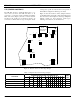
4-Wire E&M, Type I
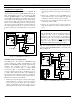
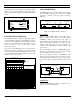
Figure 15 shows the GTI telephone interface circuit
connected per Table 1 for 4-Wire E&M, Type I. Six wires
are needed to connect to the telephone company side.
Ground for the M Lead and -48V for the E Lead are
provided by the GTI.
E Lead
M Lead
Trans-
former
former
Trans-
E-Lead Det.
4
5
3
6
2
7
To
PSTN
Rec Audio
Send Audio
-
-
-48V
8
1
4-W Send
4-W Send
4-W Rec
4-W Rec
Figure 15 - 4-Wire E&M Type I Circuit
To Reverse 4-Wire Audio
The 4-Wire audio connections shown in Table 1 require
the audio to enter the GTI on pins 4&5 and the audio to
leave the GTI on pins 3&6. To reverse this, change
jumpers JP2 and JP3 from A&C to B&D.
To Reverse E and M Leads
The jumper positions shown in Table 1 require that the E
Lead is connected to pin 7 and the M Lead to pin 2. To
reverse this, change jumpers JP6 from C&M to B&D.
To Change E-Lead Reference
The jumper positions shown in Table 1 provide a -48V
reference for the E Lead. To change this reference to
ground, change jumper JP12 from B to A.
To Change M-Lead Reference
The jumper positions shown in Table 1 provide a ground
reference for the M-Lead. To change this reference to -
48V, change jumper JP1 from M to A.