
Specifications

L
BI-39076 FIGURES AND TABLES
4
LIST OF FIGURES AND TABLES
Page:
Figure 1 - Typical Enhanced Local Interconnect System.......................................................................................... 7
Figure 2 - GTI Audio Paths ...................................................................................................................................... 8
Figure 3 - Location of Fastener Screws .................................................................................................................... 10
Figure 4 - Location of PROM Card .......................................................................................................................... 10
Figure 5 - Location of PROMs ................................................................................................................................. 10
Figure 6 - Application Software Identification ......................................................................................................... 10
Figure 7 - GTI Software Locations........................................................................................................................... 11
Figure 8 - GTI Main Software Label ........................................................................................................................ 11
Figure 9 - GTI 552 Software Label........................................................................................................................... 11
Figure 10 - GTI DSP Software Label ....................................................................................................................... 11
Figure 11 - Board Locations for Line-Type Jumpers................................................................................................ 12
Figure 12 - End-to-End Loop Start Circuit ............................................................................................................... 13
Figure 13 - End-to-End Ground Start Circuit............................................................................................................ 13
Figure 14 - 4-Wire E&M Microwave Circuit ........................................................................................................... 14
Figure 15 - 4-Wire E&M Type I Circuit................................................................................................................... 14
Figure 16 - Orientation of DIP Switches................................................................................................................... 15
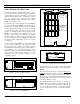
Figure 17 - GTI Circuit Board Layout...................................................................................................................... 16
Figure 18 - GTI Interface Card Software Locations ................................................................................................. 16
Figure 19 - GTI Master Software Label.................................................................................................................... 16
Figure 20 - Connections to GTI................................................................................................................................ 17
Figure 21 - Connections to ELI Interface Module .................................................................................................... 17
Figure 22 - MASTR III Connections ........................................................................................................................ 18
Figure 23 - MASTR II & IIe Connections................................................................................................................ 18
Figure 24 - PCM / Data Bus Cable ........................................................................................................................... 19
Figure 25 - Site Controller Computer Connections................................................................................................... 19
Figure 26 - IAM Software Locations........................................................................................................................ 19
Figure 27 - IAM Software Label............................................................................................................................... 20
Figure 28 - IAM DIP Switch Settings....................................................................................................................... 20
Figure 29 - IAM Rear Panel Connections................................................................................................................. 20
Figure 30 - IAM Power Supply Connections............................................................................................................ 20
Figure 31 - IAM Alarm Outputs ............................................................................................................................... 21
Figure 32 - IAM Printer RS-232 Port ....................................................................................................................... 21
Figure 33 - Local GTI Connection for 9-Pin COM Port........................................................................................... 24
Figure 34 - Local GTI Connection for 25-Pin COM Port......................................................................................... 25
Figure 35 - Front Panel of GTI Unit ......................................................................................................................... 26
Figure 36 - Front Panel of IAM ................................................................................................................................ 26
Table 1 - Jumper Positions for Telephone Line Type............................................................................................... 12
Table 2 - Defined DIP Switch Settings..................................................................................................................... 15
Table 3 - Troubleshooting Symptoms....................................................................................................................... 33