
Installation manual

INSTALLING THE MOBILE RADIO
1. Connect P202 of cable W2 from the radio to J202
on the Interconnect Board. Also connect P215 to
J215 when ORION radio is used.
2. Connect P101 of the Desk Top Station antenna ca-
ble W1 into the RF TNC connector on the radio.
3. Power Cable Connections:
a. MDX - Connect P1 of the Desk Top Assembly
power cable W3 to J1 of the radio power cable
W901.
b. ORION USA Version - Connect P1 of Desk
Top Assembly power cable W3 to J1002 on the
rear of the radio unit.
c. ORION European Version - There is no cable
W3. The power connections are included in ca-
ble W2 which connects to the DB37 connector
on the radio unit.
4. Place the radio in the mounting bracket and posi-
tion it for the proper Desk Top Station front appear-
ance and tighten the two (2) M3.5 screws that hold
the radio mounting bracket in place.
5. Replace the Desk Top Assembly cover using the
two (2) screws loosened in Step 1 of "PREPARA-
TION OF DESK TOP STATION."
This completes the installation of the mobile radio in the
Desk Top Station Assembly.
INSTALLING THE DESK TOP STATION
AC Power
The Desk Top Station power supply must be connected
to AC power with the fused and ON/OFF-switched AC
power cable found at the back of the Desk Top Assembly.
The transformer straps are shipped set for a 120 volt power
source:
120 volts ±10%, Single-Phase, 50/60 Hz, 4 amps,
500 watts
Refer to Power Supply Maintenance Manual LBI-38751
for procedures to change the transformer straps to accommo-
date a 240 volt power source:
240 volts ±10%, Single-Phase, 50/60 Hz, 2 amps,
500 watts
Different Desk Top Station power supplies may have dif-
ferent current capabilities. Refer to the applicable power su-
ply maintenance manual for current usage.
Microphone
A desk microphone, a DTMF microphone, or a standard
mobile microphone can be used. The microphone connects
to the Desk Top Station at J101 on the Front Cap under the
Control Panel.
Antenna
A 50-ohm antenna is required. It should be connected
through coax cable to the Type N connector mounted in the
rear wall of the Desk Top Assembly.
INSTALLING THE STANDBY POWER
TRANSFER OPTION
1. Loosen the two (2) captive screws holding the top
cover on the Desk Top Station Assembly. Remove the
cover.
2. Disconnect cable W3 from the station power supply at
J1/P101.
3. Mount Power Transfer Relay K1 inside to the side
wall between the power supply and speaker using the
single mounting screw supplied.
4. Remove and discard the rectangular knockout button
in the rear wall of the Desk Top Assembly. Snap P2
of BATT STBY/PWR cable into the hole.
5. Connect the relay harness as follows:
a. Connect P1 to J1 of the station power supply.
b. Connect J1 to P1 of W3.
6. Replace the Desk Top Assembly cover using the two
screws loosened in Step 1 of these instructions.
INSTALLING THE REMOTE OPTION (MDX
ONLY)
1. Remove the two (2) captive screws holding the top
cover on the Desk Top Station Assembly. Remove the
cover.
2. If the Desk Top Assembly already includes the factory
installed "Intercom Remote" Control Panel and the
Remote Interface Board, proceed to Step 6 below.
Otherwise, replace the standard Control Panel with
the "Intercom Remote" control panel.
3. Remove jumper P104 from J204 on the Interconnect
Board. Install the Remote Interface Board.
4. Mount the Remote Interface Board onto the Intercon-
nect Board, plugging it in so P204 and P205 seat di-
rectly on the horizontally oriented pins of J204 and
J205 on the Remote Interface Board.
5. Remove and discard cables included with the Remote
Board. Install the Remote Board on the base of the
station behind the Interconnect board on standoffs
with M3.5 screws. Connect the Remote Board J2 to
the Remote Interface Board J302 using cable W7.
6. Connect the Remote Interface Board J301 to the Con-
trol Panel J1 using cable W6.
7. Remove the knockout on the rear of the station for
J11. Insert J11 of cable W10. Connect the other end
of W10 to J1 or TB1 of the Remote Board per the In-
terconnect Diagram 19D904375 sheet 2.
8. Adjust operating audio levels on the Remote Board
DC Remote Board 19A704686P3 LBI-31594
Tone Remote Board 19A704686P6 LBI-31552
EDACS Remote Board 19A704686P8 LBI-38119
The Remote Control Board should be checked and adjusted
when the system is installed. The tonedecoder and filter adjust-
ments are set at the factory and should not require adjustment
unless the tone filters, decoders, generators or associated cir-
cuitryare replaced.
Make sure all connections to the base station and Remote Con-
troller are complete, and that the tone panel and base station
have been properly aligned before adjusting the Tone Remote
Control Board.
ADJUSTING THE REMOTE OPTION
Equipment Required
1. Ac voltmeter with dBm scale
2. Audio Generator
3. Deviation Monitor
Receive Audio (R2) (R35) (R66)
1. Apply a 1000 Hz tone with a ±3 kHz deviation to the sta-
tion receiver that is strong enough to fully quiet the receiver.
2. A. On the DC Remote Board 686P3 set R2 for 0dBm
at J1-1 & J1-4.
B. On the Tone Remote Board 686P6 set R35 for
0dBm at J1-3 & J1-4.
C. On the EDACS Remote Board 686P8 set R66 for
0dBm at TB1-2 & TB1-5.
Intercom Audio
1. Apply 1000hz at 30mvRMS to Mic Jack J101.
2. Turn Intercom Sw on.
3. On (931) Interface Bd Set R323 for OdBm at:
a. J1-1 & J1-4 on the 686P3 DC Remote Bd.
b. J1-3 & J1-4 on the 686P6 Tone Remote Bd.
c. TB1-2 & TB1-5 on the 686P8 EDACS Remote
Bd.
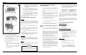
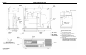
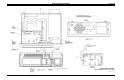
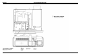
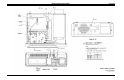
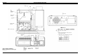
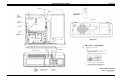
Figure 1 - Desk Top Station Assembly (MDX Radio Shown)
The Desk Top Station may not operate properly with
the antenna mounted near the radio. Always mount
the antenna at least five (5) feet from the station.
CAUTION
LBI-38977
2