
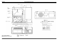
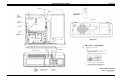
Installation manual

Tx Mic Audio (R1) (R60) (R82)
1. Apply a 1000 Hz tone at 120mV into the microphone
jack of the Remote Controller with the largest line
loss (usually farthest from the station).
2. If the mobile will not key from the remote and/or the
Remote SF functions do not work.
a. On the Tone Remote 686P6 Bd. adjust R59 until it
does.
b. On the EDACS Remote 686P8 Bd. adjust R17
until it does. (R16 may also require adjustment.
Use R16 only if needed.)
3. A. On the 686P3 DC Remote Board set R1 for the
proper deviation.
B. On the 686P6 Tone Remote Board set R60 for the
proper deviation.
C. On the 686P8 EDACS Remote Board set R82 for
the proper deviation.
For detailed instructions, refer to the applicable mainte-
nance manual for the board being adjusted. The audio levels
on the Remote Board must be adjusted first, before the two in-
tercom level adjustments can be made on the Remote Interface
Board.
Speaker Level
1. After the Remote Board is set up so that the remote
consoles are transmitting and receiving properly with
the Desk Top Station radio, adjust the intercom levels
on the Remote Interface Board:
a. Adjust R325 for the proper station speaker level
from the remote console microphone.
2. Replace the Desk Top Assembly cover with the two
(2) screws loosened previously.
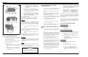
INSTALLING THE KEYPAD BOARD
OPTION (MDX ONLY)
1. Loosen the two (2) captive screws holding the top
cover on the Desk Top Station Assembly. Remove the
cover.
2. Mount the Keypad Board onto the Interconnect
Board, plugging it in so that P207 and P208 seat di-
rectly on the horizontally oriented pins of J207 and
J208 on the Interconnect Board.
3. Connect the end of W9 marked "keypad" onto the
keypad pins. Plug the other end onto J401 of the Key-
pad Board. Observe keyed pins of W9.
4. When remote options are used, connect cable W8 to
P2 of the Remote Board. Connect the other end to
J402 of the Keypad Board. Orient plug at J402 so the
pin with no wire is toward J208.
5. On Remote Interface Board connect jumpers as fol-
lows:
P303 on J303 pins 2 and 3
P304 on J304 pins 2 and 3
P305 on J305 pins 2 and 3
P306 on J306 pins 2 and 3
P307 on J307 pins 2 and 3
6. Replace Desk Top Assembly cover with the two (2)
screws loosened in Step 1.
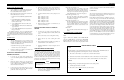
INSTALLING THE CLOCK/VU MODULE
OPTION
1. Loosen the two (2) captive screws holding the top
cover on the DeskTop Station Assembly. Remove the
cover.
2. Remove the four (4) screws securing the Front Cap.
3. Remove the four (4) screws securing the Control
Panel.
4. Remove P106 from the Power LED, note polarity. On
Control Panel remove P1 of W6 from J1.
5. Install new 904861G5 or G6 by reversing the order of
steps 1-4.
CLOCK SETTING INSTRUCTIONS
The following separate items may be set: 12/24 hr display
mode, hours, minutes, and display intensity. The time keeping
stops when in any of the set modes. The clock seconds (not
displayed) are set to zero any time a display is altered. Thus, if
setting to the nearest second is desired, the operator must set
the time one minute ahead of the presetn time then wait for the
reference clock to advance to the displayed time before exiting
the set mode. To set the clock:
• Press SW1 approximately 1 sec.
A "12__" or "24__" will display indicating the display
mode. Press SW2 to alternate between modes. When
the correct mode is displayed.
• Press SW1 approximately 1 sec.
The time will display (no flashing colon) with
hours intensified. Press SW2 to advance the hours.
Holding SW2 down will auto increment at about 3
counts per second. Note the dot in the upper left in-
dicates PM. When the correct hour is displayed.
• Press SW1 approximately 1 sec.
The time will display with minutes intensified.
Press SW2 to advance the minutes. When the cor-
rect minutes are displayed.
• Press SW1 approximately 1 sec.
The time will display at the set intensity (no flash-
ing colon). SW2 changes the intensity. Four intensi-
ties are available. When the correct intensity is
displayed and the reference clock advances to the
next minute.
• Press SW1
The colon will now flash and the time keeping con-
tinues.
VU METER TEST/CALIBRATION
TEST
Apply a 1 kHz tone at OVRMS to J101-1 DESK MIC HI
and J101-2 DESK MIC LO. Ground J101-3 DESK MIC
PTT. No LEDs should be lit. Increase 1 kHz tone level. The
LEDs should turn on one at a time. All green/yellow LEDs
should be lit at a level of 100 mV. All red LEDs should be lit
at a level of 175 Mv.
CALIBRATION
The VU meter should have been calibrated at the factory. If
the dot at the lower right hand corner of the display is lit,
then calibration must be performed.
If the calibration must be changed, a calibration mode is en-
tered by removing power from the unit, then while holding
down SW1, powering the unit. The unit will display a 3 digit
number. Supply a 107 mV 1 kHz signwave to the Desk Mic
Hi input (J101-1 & 2) and ground the Desk Mic PTT input
(J101-3). The bar graph will operate. SW1 will increase the
gain (decrease the displayed number) while SW2 will de-
crease the gain. These switches must be tapped, not held to
set the gain. The range of the displayed number is 80 to 205
with 128 being the default (typical calibration value). In-
crease the gain until one red bar lights, then decrease the
gain until this red light goes out. This is the ideal calibration
point. To exit the calibrate mode and store this calibration
constant and the key, press and hold down SW1 for about 5
seconds. The module will resume normal operation.
The VU meter bar graphic display is inactive during the
time setting mode.
NOTE
PROGRAMMING NOTES
MDX
PC Programming is accomplished through jack J101 on the desktop station. The MDX mobile can
only be flashed programmed via the microphone connector on the radio unit.
1. The volume control must be set to level seven (7) and the enable activated.
2. When the remote interface board is installed, the volume control must be set for fixed volume.
3. When the station is local control only, the volume control must
not be set for fixed volume.
ORION
PC Programming is accomplished through jack J101 on the desktop station.
1. Auxiliary input #2 must be set to PTT.
2. The volume control is
not fixed for the local control station.
LBI-38977
3