LBI-38898 Mobile Communications EDACS-2 UTILITY PROGRAMMING Maintenance Manual
LBI-38898 TABLE OF CONTENTS Page INTRODUCTION ................................................................ TRACKING DATA ...................................................... SYSTEM HOOK-UP (PCS Only)................................ System Hook-Up Procedure .................................. 3 3 4 5 MAINTENANCE................................................................. 7 CALIBRATION FREQUENCIES (PCS Only)................... 8 CALIBRATION (PCS Only) .........................................
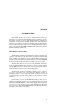
LBI-38898 INTRODUCTION This manual describes the operation of the EDACS-2 Utility Software that is provided with TQ-3346/TQ-3373 Programming software. The Utility Software is used to make Final Transmitter and Receiver Alignments on the Dual Format PCS portable radio. This manual describes how to calibrate and adjust the Tracking Data in the PCS radio using the Utility Program.
LBI-38898 SYSTEM HOOK-UP (PCS Only) Connect all peripheral equipment to your computer prior to configuring the PC Programming Software items. Remember to refer to the operating manuals of each device for correct installation procedures. If your system is already established, check to see that you have all the equipment necessary to execute the program. Isolate all cables connecting the computer to devices to prevent tangling, interference and damage.
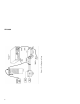
LBI-38898 System Hook-Up Procedure (Refer to Figure 1) 1. Locate a serial port on your computer. This port will usually be located at the rear of the computer. However, since this is dependent upon the design of your computer, refer to the computer operator’s manual for directions. The IBM PC/XT/AT systems support up to two serial ports. There are two physical standards for the serial port configurations of personal computers.
Figure 1 - Test Equipment Setup (TYPICAL) LBI-38898
LBI-38898 5. Connect the remaining Test Equipment as shown in Figure 1. 6. If the TQ-3346/TQ-3373 software has not been installed previously on the computer, install the software as described in the TQ-3346/TQ3373 manual. MAINTENANCE First place the PCS radio into PC programming mode. Simultaneously push one of the volume switches (UP or DOWN) along with one of the channel switches (UP or DOWN), turn on radio power, and then release the buttons.
LBI-38898 From the Maintenance Window, your options are: F1-Calib Select this option if you want to: Align the power, modulation and squelch settings across the band. F2-Track Select this option if you want to: Edit the radio tracking data and then update the values in the radio. F3-Featur Select this option if you want to: Edit the Feature Authorization data. F4-Freq Select this option if you want to: Modify the frequencies used for calibration.
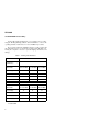
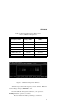
LBI-38898 Table 2 - Band Segment Fequency Ranges And Factory Calibration Frequencies Frequency Band Range (MHz) Factory Calibration (MHz) LOW 806-813 806.0125 MID 813-821 813.0125 HIGH 821-824 824.0125 LOW Talkaround 851-858 851.0125 MID Talkaround 858-866 858.0125 HIGH Talkaround 866-869 869.0125 Figure 3 - Calibration Frequencies Window All fields represent the TX frequency and are numeric. Make the desired changes and press F10 Back to exit.
LBI-38898 Shift F9 Window Help Select this option if you want to: Receive further information pertaining to the present window. F10-Back Select this option if you want to: Return to the Maintenance Screen. CALIBRATION (PCS Only) TX POWER Figure 4 - TX Power Window NOTE While adjusting the radio, DO NOT disconnect the radio from the PC interface at any time.
LBI-38898 viewed/edited by returning to the main screen by pressing F10 Back, and pressing F4 Freq. Upon pressing F4 Tx On, the programmer will put the radio into transmit mode. The screen will display a blinking field, "TRANSMITTER ON", to indicate that the radio is transmitting. The radio will remain in transmit mode until F4 Tx Off is pressed, or the timeout period (about 2 minutes) has been exceeded.
LBI-38898 TX Power Settings High Power Settings 1. The "Tx High Power Calibration" window should be on the screen. If this window is not on the screen, then use the F1 Next or F2 Prev keys to toggle to the correct window. 2. Press F4 Tx On to key the transmitter. 3. Measure the transmitter power output. 4. With the Low Frequency value highlighted, increment or decrement the current value (Hex or Decimal) until the specified window for power is reached. See Table 3. 5.
LBI-38898 Table 3 - High And Low Power Specifiations HIGH POWER FREQUENCY LOW POWER Power (Watts) I(Amps) Power (Watts) I(Amps) TX Low 3.2 ±0.1 <2.0 1.1 ±0.1 <1.3 TX Mid 3.2 ±0.1 <2.0 1.1 ±0.1 <1.3 TX High 3.2 ±0.1 <2.0 1.1 ±0.1 <1.3 TX Low Talkaround 2.5 ±0.1 <2.0 1.1 ±0.1 <1.3 TX Mid Talkaround 2.5 ±0.1 <2.0 1.1 ±0.1 <1.3 TX High Talkaround 2.5 ±0.1 <2.0 1.1 ±0.1 <1.3 Low Power Settings 1.
LBI-38898 From TX Power window, your options are: F1-Next Select this option if you want to: Advance the screen to the next setting which can be adjusted. F2-Prev Select this option if you want to: Return the screen to the previous setting which can be adjusted. F3-Decimal/Hex Select this option if you want to: Toggle the input fields on the screen between decimal and hexadecimal. F4-Tx On/Tx Off Select this option if you want to: Key or unkey the radio.
LBI-38898 TX MODULATION Figure 5 - TX Modulation Window NOTE While adjusting the radio, DO NOT disconnect the radio from the PC interface at any time. The TX Modulation Window, shown in Figure 5, is accessed by selecting F1 Calib from the Maintenance Screen and then F1 Next or F2 Prev until the window appears. This window allows the user to align the Transmit Modulation setting across the band.
LBI-38898 In addition to entering a value from the keyboard, there are key actions available as described below: <+> Increments the field by 1 and writes the new value to the radio if the transmitter is on. <-> Same as <+> only it decrements. ↑↓→← Arrow keys move the cursor between fields on the screen. From Figure 5: (1) This is a numeric field that is used to set the Transmit Modulation level.
LBI-38898 NOTE The MIC HI input line to the PCS is also the RX DATA line from the computer. To allow simultaneous communication with the computer while feeding in a 1 kHz tone, the audio generator impedance must be 600 ohms or greater. Insert a resistor in series with the generator output if necessary, i.e. a 560 ohm resistor when using a 50 ohm generator. Also, higher audio signal levels exceeding 200 mV rms may confuse the radio as being data. 2.
LBI-38898 7. Repeat steps 4-6 for each frequency. From TX Modulation Window, your options are: F1-Next Select this option if you want to: Advance the screen to the next setting which can be adjusted. F2-Prev Select this option if you want to: Return the screen to the previous setting which can be adjusted. F3-Decimal/Hex Select this option if you want to: Toggle the input fields on the screen between decimal and hexadecimal. F4-Tx On/Tx Off Select this option if you want to: Key or unkey the radio.
LBI-38898 DATA MODULATION Figure 6 - Data Modulation Window NOTE While adjusting the radio, DO NOT disconnect the radio from the PC interface at any time. The Data Modulation Window, shown in Figure 6, is accessed by selecting F1 Calib from the Maintenance Screen and then F1 Next or F2 Prev until the window appears. This window allows the user to align the data modulation setting across the band.
LBI-38898 will display a blinking field, "TRANSMITTER TIMEOUT", for a short period of time. In addition to entering a value from the keyboard, there are key actions available as described below: <+> Increments the field by 1 and writes the new value to the radio if the transmitter is on. <-> Same as <+> only it decrements. ↑↓→← Arrow keys move the cursor between fields on the screen. From Figure 6: (1) This is a numeric field that is used to align the data modulation level.
LBI-38898 4. Press F4 Tx Off to key the transmitter. 5. Repeat steps 2-6 for each frequency. Table 5 - Data Deviation Specifications FREQUENCY DEVIATION (kHz) TX Low 3.0 ±0.1 TX Mid 3.0 ±0.1 TX High 2.4 ±0.1 From Data Modulation Window, your options are: F1-Next Select this option if you want to: Advance the screen to the next setting which can be adjusted. F2-Prev Select this option if you want to: Return the screen to the previous setting which can be adjusted.
LBI-38898 SQUELCH Figure 7 - Squelch Window NOTE While adjusting the radio, DO NOT disconnect the radio from the PC interface at any time. The Squelch Window, shown in Figure 7, is accessed by selecting F1 Calib from the Maintenance Screen and then F1 Next or F2 Prev until the window appears. This window allows the user to align the squelch setting. Upon pressing F4 Rx On, the programmer will put the radio into receive mode.
LBI-38898 From Figure 7: (1) This field indicates the current band split selected. (2) This is a numeric field that is used to align the receive squelch opening level. This field will accept any hex value from 90 - E2 and any decimal value from 144-226, depending on the current state of the screen (Hexadecimal or decimal) displays. The bar indicator changes with and provides a direct representation of the value of this field.
LBI-38898 MHz above the specified TX frequency. For Talkaround selections, the receive frequency will be the same as the specified TX frequency. 3. Press F4 to toggle the RX audio on. 4. Move down to the Value Field and change the value to "E2 for hex or 226 for decimal". This will open the receiver squelch. 5. With the RF generator at -117.0 dBm, modulated with a 1 kHz tone at 3 kHz deviation, reduce generator RF level until 8-10 dB SINAD is found across the RX AUDIO jacks on the TQ-0613 Test Box. 6.
LBI-38898 TRACKING DATA (PCS Only) Figure 8 - Tracking Data Window This window is used to edit the radio tracking data (in hexadecimal format only). Once the desired values have been entered, press F5 Prog to update the values in the radio. From the Tracking Data Window, your options are: F5-Prog Select this option if you want to: Program the radio with the new tracking data values. F9-Help Select this option if you want to: Receive further information pertaining to a field area.
LBI-38898 FEATURES (Includes MDR, MDX And PCS) Figure 9 - Features Window WARNING Changing the data on this screen can disable the radio. The Feature Authorization Window, shown in Figure 9, is accessed by selecting F3 Featur from the Maintenance Screen. This window is used to Read, Write or Edit the Feature Authorization Data in the radio. Highlight one of these options and press .
LBI-38898 NOTES 27
Printed in U.S.A.