LBI-38847B Mobile Communications MDX SERIES MOBILE RADIO Printed in U.S.A.
OPTION INTERCONNECTION DIAGRAM TABLE OF CONTENTS INTRODUCTION . . . . . . . . . . . . . . . . . . . . . . . . . 3 UNPACKING AND CHECKING EQUIPMENT . . . . . . . . . 3 PLANNING THE INSTALLATION . . . . . . . . . . EQUIPMENT REQUIRED . . . . . . . . . . . . INSTALLATION IN VEHICLES POWERED BY LIQUEFIED (LP) GAS . . . . . . . . . . . . MOUNTING LOCATION . . . . . . . . . . . . . . . . . . . 4 . . . . . . 6 INSTALLATION . . . . . . . . RUNNING CABLES . . . MOUNTING THE RADIO MICROPHONE HANGER MICROPHONE . . .
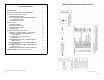
OPTION INTERCONNECTION DIAGRAM INTRODUCTION This manual contains installation instructions for the MDX Mobile Radio series and associated accessories. These instructions cover the mounting and cabling of the radio; interconnection diagrams are provided at the back of the manual for reference. Before installation, the radio should be programmed using an IBM compatible personal computer and the following items: Serial Programming Interface Module Kit . . . . . . . . . . . . Programming Cable . . . . . . . .
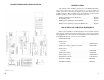
Table 1 - MDX Mobile Radio Series Optional Accessories Option Description Part Number PMAN1L 800 MHz roof mount antenna with TNC connector 19B209568P5 PMCC9M External speaker cable, 18 inches 19A149590P8 PMCD1W External speaker cable, 16 feet, requires option PMZM1K and PMCD7Z 19A149590P10 PMCD7Z External option cable, 2 feet 19C851585P14 PMCD9A Power cable, 18 feet 19801358P17 PMLS1F Speaker, MIL-STD-810C & D, 5" x 5", requires options PMCD7Z & PMCC9M 19A149590P1 PMMC3X Desk microphon
OPTION INTERCONNECTION DIAGRAM • • out of the way of auto mechanics. out of the way of passengers. It is suggested that the radio be installed by one of the many authorized General Electric Service Stations located throughout the United States. These experienced service stations can provide a proper radio installation and make any final adjustments that may be needed.
EQUIPMENT REQUIRED NOTES The equipment required for installing the MDX Mobile Radio is listed below: • • • • • • • Electric drill for drilling mounting holes. Drills and circle cutters as follows: • No. 31 (1/8-inch) drill for No. 8 self-tapping screws. • No. 27 (9/64-inch) drill for No. 10 self-tapping screws. • 5/8-inch drill or circle cutter for power cable. • 3/4-inch circle cutter, hole saw or socket punch for antenna (optional).
INSTALLATION IN VEHICLES POWERED BY LIQUEFIED (LP) GAS NOTES Radio installation in vehicles powered by liquefied petroleum gas with the LP-gas container in the trunk or other sealed-offspace within the interior of the vehicle must conform to the National Fire Protection Association Standard NFPA 58 which requires that: • • • Space containing radio equipment shall be isolated by a seal from the space containing the LP-gas container and its fittings.
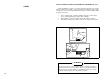
INSTALLATION NOTES RUNNING CABLES To assure the feasibility of the planned cable routings. it is suggested that the cables be run before mounting the radio. Be sure to leave some slack in each cable going to the radio so that the radio may be pulled out for servicing with the power applied and antenna attached. Try to route the cables away from locations where they will be exposed to heat (exhaust pipes, mufflers, tailpipes. etc.).
4. Push the prepared fuse connectors into each section of the fuse holders. Place the fuse into a fuse holder section until it seats within the connector. Connect the fuse holder sections to insure a tight fit and connection.
Connect the orange fused lead to the positive (+) battery terminal, and black to the negative (-) battery terminal. Always locate the fuse as close to the battery as possible. Connect the red fused lead to the ignition on" sense point (preferably an "Accessory" point on the fuse panel that is switched on when the ignition switch is in the accessory position and in the "run" position). Locate the fuse as close as possible to the accessory point.
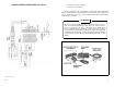
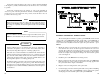
ALARM (HORN) RELAY KIT - OPTION PMSUIC (19A705499P1) Requires the use of option cable kit - option PMCC3N.
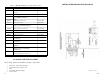
Table 2 - Option Cable Connections Pins Function P2-1 A- P2-2 SPEAKER LO P2-3 SPEAKER HI P2-4 MIC HI P2-5 SW A+ P2-6 SERIAL REQUEST (GE-STAR) P2-7 PTT P2-8 CG DISABLE P2-9 SW SPEAKER HI P2-10 AUDIO MUTE P2-11 VOLUME-SQUELCH HI P2-12 MIC LO P2-13 RELAY P2-14 SPARE POWER CABLE (18 FEET) - OPTION PMCD9A (19B801358P17) Refer to the power and ignition cable installation section starting on page 8 to install this optional power cord.
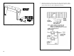
Figure 6 - Microphone Hanger Figure 8- Option Cable Pin Locations NOTE If mounting on a surface covered with carpet, punch holes with a small punch then make a small slit in the carpet, insert a short piece of metal tubing and drill through the tubing. Use the following procedure to mount the microphone hanger: 1. Use the hanger as a template to mark the screw locations and drill the three small pilot holes. 2. Use the self tapping screws to mount the hanger in an upright position.
MICROPHONE The microphone connects to the MDX Mobile Radio using a plug found at the end of its attached cable. Match the pins on this plug to the pin socket on the radio and press in the plug being sure not to damage the pins. Once the plug is seated, tighten down the plug using the thumbscrew on the mic connector. To remove the plug reverse this procedure. A permanent mount type of antenna should be located in the center of the roof of center of rear deck.
MICROPHONE The microphone connects to the MDX Mobile Radio using a plug found at the end of its attached cable. Match the pins on this plug to the pin socket on the radio and press in the plug being sure not to damage the pins. Once the plug is seated, tighten down the plug using the thumbscrew on the mic connector. To remove the plug reverse this procedure. A permanent mount type of antenna should be located in the center of the roof of center of rear deck.
Figure 6 - Microphone Hanger Figure 8- Option Cable Pin Locations NOTE If mounting on a surface covered with carpet, punch holes with a small punch then make a small slit in the carpet, insert a short piece of metal tubing and drill through the tubing. Use the following procedure to mount the microphone hanger: 1. Use the hanger as a template to mark the screw locations and drill the three small pilot holes. 2. Use the self tapping screws to mount the hanger in an upright position.
Table 2 - Option Cable Connections Pins Function P2-1 A- P2-2 SPEAKER LO P2-3 SPEAKER HI P2-4 MIC HI P2-5 SW A+ P2-6 SERIAL REQUEST (GE-STAR) P2-7 PTT P2-8 CG DISABLE P2-9 SW SPEAKER HI P2-10 AUDIO MUTE P2-11 VOLUME-SQUELCH HI P2-12 MIC LO P2-13 RELAY P2-14 SPARE POWER CABLE (18 FEET) - OPTION PMCD9A (19B801358P17) Refer to the power and ignition cable installation section starting on page 8 to install this optional power cord.
ALARM (HORN) RELAY KIT - OPTION PMSUIC (19A705499P1) Requires the use of option cable kit - option PMCC3N.
Connect the orange fused lead to the positive (+) battery terminal, and black to the negative (-) battery terminal. Always locate the fuse as close to the battery as possible. Connect the red fused lead to the ignition on" sense point (preferably an "Accessory" point on the fuse panel that is switched on when the ignition switch is in the accessory position and in the "run" position). Locate the fuse as close as possible to the accessory point.
4. Push the prepared fuse connectors into each section of the fuse holders. Place the fuse into a fuse holder section until it seats within the connector. Connect the fuse holder sections to insure a tight fit and connection.
INSTALLATION NOTES RUNNING CABLES To assure the feasibility of the planned cable routings. it is suggested that the cables be run before mounting the radio. Be sure to leave some slack in each cable going to the radio so that the radio may be pulled out for servicing with the power applied and antenna attached. Try to route the cables away from locations where they will be exposed to heat (exhaust pipes, mufflers, tailpipes. etc.).
INSTALLATION IN VEHICLES POWERED BY LIQUEFIED (LP) GAS NOTES Radio installation in vehicles powered by liquefied petroleum gas with the LP-gas container in the trunk or other sealed-offspace within the interior of the vehicle must conform to the National Fire Protection Association Standard NFPA 58 which requires that: • • • Space containing radio equipment shall be isolated by a seal from the space containing the LP-gas container and its fittings.
EQUIPMENT REQUIRED NOTES The equipment required for installing the MDX Mobile Radio is listed below: • • • • • • • Electric drill for drilling mounting holes. Drills and circle cutters as follows: • No. 31 (1/8-inch) drill for No. 8 self-tapping screws. • No. 27 (9/64-inch) drill for No. 10 self-tapping screws. • 5/8-inch drill or circle cutter for power cable. • 3/4-inch circle cutter, hole saw or socket punch for antenna (optional).
OPTION INTERCONNECTION DIAGRAM • • out of the way of auto mechanics. out of the way of passengers. It is suggested that the radio be installed by one of the many authorized General Electric Service Stations located throughout the United States. These experienced service stations can provide a proper radio installation and make any final adjustments that may be needed.
Table 1 - MDX Mobile Radio Series Optional Accessories Option Description Part Number PMAN1L 800 MHz roof mount antenna with TNC connector 19B209568P5 PMCC9M External speaker cable, 18 inches 19A149590P8 PMCD1W External speaker cable, 16 feet, requires option PMZM1K and PMCD7Z 19A149590P10 PMCD7Z External option cable, 2 feet 19C851585P14 PMCD9A Power cable, 18 feet 19801358P17 PMLS1F Speaker, MIL-STD-810C & D, 5" x 5", requires options PMCD7Z & PMCC9M 19A149590P1 PMMC3X Desk microphon
OPTION INTERCONNECTION DIAGRAM INTRODUCTION This manual contains installation instructions for the MDX Mobile Radio series and associated accessories. These instructions cover the mounting and cabling of the radio; interconnection diagrams are provided at the back of the manual for reference. Before installation, the radio should be programmed using an IBM compatible personal computer and the following items: Serial Programming Interface Module Kit . . . . . . . . . . . . Programming Cable . . . . . . . .
OPTION INTERCONNECTION DIAGRAM TABLE OF CONTENTS INTRODUCTION . . . . . . . . . . . . . . . . . . . . . . . . . 3 UNPACKING AND CHECKING EQUIPMENT . . . . . . . . . 3 PLANNING THE INSTALLATION . . . . . . . . . . EQUIPMENT REQUIRED . . . . . . . . . . . . INSTALLATION IN VEHICLES POWERED BY LIQUEFIED (LP) GAS . . . . . . . . . . . . MOUNTING LOCATION . . . . . . . . . . . . . . . . . . . 4 . . . . . . 6 INSTALLATION . . . . . . . . RUNNING CABLES . . . MOUNTING THE RADIO MICROPHONE HANGER MICROPHONE . . .
LBI-38847B Mobile Communications MDX SERIES MOBILE RADIO Printed in U.S.A.