LBI-38846B Operator’s Manual ® EDACS MDX MOBILE RADIO ericssonz
TABLE OF CONTENTS Page SAFETY INFORMATION . . . . . . . . . . . . . . . . . . . . 5 SAFE DRIVING RECOMMENDATIONS FOR USERS OF MOBILE RADIOS . . . . . . . . . . . . . . . . . . . 6 OPERATING PROCEDURES . . . . . . . . . . . . . . . . . . 6 INTRODUCTION . . . . . . . . . . . . . . . . . . . . . . . . 8 CONTROLS, INDICATORS, AND DISPLAYS CONTROLS . . . . . . . . . . . . . . . . DISPLAY INDICATORS . . . . . . . . . DISPLAY ALPHA INDICATORS . . . . Full Length Indicators . . . . . . . . Abbreviated Indicators .
TABLE OF CONTENTS (CON’T) SELECTING SYSTEM/GROUP/CHANNEL . . . . Group Selection . . . . . . . . . . . . . . . . . System Selection . . . . . . . . . . . . . . . . Channel Selection (Conventional System) . . . FRONT PANEL SQUELCH ADJUSTMENT . . . . INTERNAL/EXTERNAL SPEAKER . . . . . . . . MICROPHONE PUBLIC ADDRESS OPERATION . . . . . . . . . . . . . . Page . 22 . 22 . 22 . 23 . 23 . 23 . 23 EDACS TRUNKED OPERATION . . . . . . . . . . . . . . . PLACING A TRUNKED DISPATCH CALL . . . . . . .
TABLE OF CONTENTS (CON’T) Page Placing A Telephone Interconnect Call (On Systems Equipped With Interconnect Hardware) Answering A Telephone Interconnect Call . . . . . . Placing A Special Call To Another Radio . . . . . . Receiving An Individual Call . . . . . . . . . . . . DIRECT MODE OPERATION . . . . . . . . . . . . . . . 37 . 38 . 38 . 39 . 39 CONVENTIONAL MODE OPERATION . . . . . . . . . . . . 40 RECEIVING A CALL . . . . . . . . . . . . . . . . . . . . 40 SENDING A MESSAGE . . . . . . . . . . . . . .
SAFETY INFORMATION The operator of any mobile radio should be aware of certain hazards common to the operation of vehicular radio transmissions. A list of possible hazards are: 1. Explosive Atmospheres Just as it is dangerous to fuel a vehicle with the motor running, be sure to turn the radio off while fueling the vehicle. Do not carry containers of fuel in the trunk. 2. Interference to Vehicular Electronics Systems Electronic fuel injection systems, electronic anti skid braking systems, etc.
5. Liquefied (LP) Gas Powered Vehicles Mobile radio installations in vehicles powered by liquefied petroleum gas with the LP gas container in the trunk or other sealed-off space within the interior of the vehicle must conform to the National Fire Protection Association standard (NEPA) 58 which requires that: a. The space containing the radio equipment shall be isolated by a seal from the space containing the LP gas container and its fittings. b.
1. It is a violation of FCC rules to interrupt any distress or emergency message. As the radio operates in much the same way as a telephone "party line", always listen to make sure that the line is clear - that no one else in on the air - before sending messages. If someone is sending an emergency message - such as reporting a fire, or asking for help in an accident - KEEP OFF THE AIR! Emergency calls have priority over all other messages. 2.
INTRODUCTION This manual describes how to use the EDACS MDX Mobile Radio. The MDX is a synthesized, microprocessor-based, high performance simplex mobile FM radio providing reliable two-way communications in both the GE-MARC and Enhanced Digital Access Communications System (EDACS) trunking environments. If your MDX is equipped with the Aegis Digital Voice or Encrypted Digital Voice option, the GE-MARC mode of operation is no longer available.
CONTROLS, INDICATORS, AND DISPLAYS The MDX Scan radio contains ten buttons, an eight character DOT MATRIX display and seven indicators. The MDX System radio contains ten buttons, an eight character DOT MATRIX display and seven indicators along with a twelve button keypad. In addition, there are times when part of the eight character display is used to display the radio status. Backlighting on buttons illuminate Digital Legends. CONTROLS POWER Momentary push-push switch. Press once to turn the radio ON.
PUBLIC ADDRESS: Press the MENU button until "PUB ADDR" appears in the display. Press PTT to transmit in PA mode. SCAN ADD/DELETE: Press the MENU button until "SCAN A/D" appears in the display. Use the GROUP/SEL- button to step through the group selections for the current system. Use the GROUP/SEL + button to change the scan state. An "S" is illuminated to the right of the display if the group/channel has SCAN enabled. ALARM ON/OFF: Press the MENU button until "ALM ON" or "ALM OFF" appears in the display.
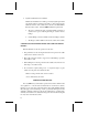
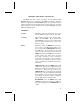
CONTROLS AND INDICATORS 8-Character Alphanumeric Dot Matrix LED allows you to identify group and system selections by descriptive names. Group/area/system names, telephone numbers, menu options, and status information are displayed here.
8-Character Alphanumeric Dot Matrix LED allows you to identify group and system selections by descriptive names. Group/area/system names, telephone numbers, menu options, and status information are displayed here.
CONTROLS (CONT’D) SYS Momentary switch. The SYS (SYSTEM) button is used to select system changes. System may be incremented by pressing and releasing the SYS button. Alternately, when the display shows the System name, the GROUP/SEL buttons may be used to increment or decrement the system selections.
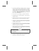
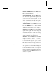
DISPLAY INDICATORS The radio’s display is shown below. The character line is used to display system or area and group or channel names and also operational messages to the user. The line contains eight Dot Matrix LED characters. The 7 status indicators are used to show the various operating conditions of the radio. Figure 3 - Sample MDX Display TX On indicates the radio is transmitting. BSY Lights when a group is active (trunked system) or when a channel is busy (conventional system).
or left of the display (PC programmable). It is separated from the normal information with an indicator such as an asterisk ("*"). Full Length Indicators **INDV** Displayed when your unit receives an individual call from another unit. ID##### If programmed, displayed when your unit receives an individual call where ##### is the unit ID of the calling radio. (Note: If the ID is in your Special Call list, you may choose to show an 8 character name instead of the number.
C* Displayed when an individual call has been received and not answered. By selecting Special Call in menu mode, the call can be recalled for return at a later time. (Note: The call is not saved through a power cycle.) E* Displayed when an active voice call on a trunked system is in an emergency state. ALERT TONES The EDACS MDX radio generates a set of unique alert tones to indicate operating status.
CALL RECEIVED If programmed, a single alert tone sounds when a group call is received and a two tone alert (one high followed by one low tone) is sounded for an individual call. CALL DISABLED ALERT You will hear a continuous low pitched tone when your radio is set to an Rx (decode) only group/channel and you press PTT on the microphone. This tone indicates that you are not allowed to place a call on this setting.
system. This happens if the unit is an invalid user or if the unit is requesting an unavailable service. Continuous Alert Tones CALL QUEUED If you hear two short, high pitched beeps after you key the microphone, the system has placed your request in a queue. The tones sound at both your transmitting unit and the receiving unit(s). This indicates to the receiving unit(s) that they will receive a call shortly. These tones will repeat every half second at the caller’s radio until Push-To-Talk is released.
cates a channel was acquired and is ready for normal conversation. INVALID CALL ORIGINATE ALERT A low frequency tone is sounded for one second immediately after pressing PTT and the display does not show WAIT. This indicates a call was attempted within a group that is not enabled for call originate or an invalid dispatch overdial call was attempted. SYSTEM TONES A low frequency tone is sounded for one second after attempting to place a trunked call and BUSY will be displayed.
OPERATING NOMENCLATURE TRUNKED OPERATION (EDACS OR GE-MARC) Trunked operation refers to the use of a set of radio frequency channels by multiple user groups. Users may place and receive calls to single or multiple users without being monitored by other users (or group) on the system. CONVENTIONAL OPERATION All radios on a conventional system operate in one of two modes: repeated or talk-around. Talk-around (also referred to as "direct mode") provides a direct radio-to-radio short-range communications link.
Wide Area System Operation (Optional) This function applies when your systems are networked together in a multi-site configuration. In this mode, your calls are automatically routed to the proper system. You may notice a delay when you press the PTT button while the system is connecting the correct sites. The BSY indicator will be on, indicating you are on the voice channel. In this mode, you can release and press PTT again to override the delay.
unit, all other radios in that group will receive a "System Busy" tone if they try to access the system. OPERATING THE RADIO TURNING THE RADIO ON 1. Push the POWER switch. The display shows the group alpha name once power up is complete. When powering up, the last selected Group or Channel should be displayed unless the radio is programmed for a pre-programmed power up System/ Group. The radio optionally generates a beep once the power up sequence is complete.
A tone sounds each time a System name changes. On units with Automatic Log in for Multi-site Operation, the radio transmits briefly after a system change. Channel Selection (Conventional System) To select a different channel when you have selected a conventional system: 1. Press the GROUP/SEL + or - ramp button until the desired channel name appears in the alphanumeric display. A tone sounds each time the channel name changes unless the BSY indicator is on.
1. Make sure the radio is turned ON. 2. Press the MNU button until PUB ADDR appears in the display. Press the PTT switch to transmit the microphone audio to the external speaker. 3. When the PA operation is completed, press the CLR button to return to normal operation. OR 1. Make sure the radio is turned ON. 2. Press the A1 or A2 button (pre-programmed). When PUB ADDR appears in the display press the PTT switch to transmit the microphone audio to the external speaker. 3.
NOTE In rare instances, several low pitched, fast "chirps" will be heard before the Call Originate tone sounds. This is caused by your radio automatically re-trying to gain access to the system after the first attempt failed (Auto-Retry). This normally occurs in fringe areas and in heavily used systems. The Auto-Retry is one of the features utilized by the radio system to provide reliable communications under adverse conditions. MANUALLY ENTERING A GROUP ID (System Model Only) 1.
From A Scanned Group When you receive an emergency call from a scanned Group (scan operating), the display shows the scanned Group’s name with the first two characters replaced by the emergency indicator (typically "E*"). The BSY indicator comes on, and you hear the Emergency tone. The display will flash until the BSY indicator goes out and the radio returns to normal operation. SENDING AN EMERGENCY MESSAGE To send an Emergency call to the selected (or Home) System/ Group, proceed as follows: 1.
Placing A Telephone Interconnect Call (On Systems Equipped With Interconnect Hardware) 1. Make sure the radio is turned ON, and the proper System has been selected. Press the MENU button until the name SPC CALL appears in the display. Press the GROUP/SEL + or - buttons until the desired name appears in the display. The number may be entered manually on the 12 button keypad of the System Model radio. 2. Press the PTT button momentarily and release for a pre-programmed number.
Placing A Special Call To Another Radio 1. Make sure the radio is turned ON, and the proper System has been selected. Press the MENU button until the name SPC CALL appears in the display. Press the GROUP/SEL + or - buttons until the desired name appears in the display. The radio ID may be entered manually if using the MDX System Model radio. 2. Press the PTT button and wait for the channel available tone before talking. 3. When completed, release the PTT button and listen for any reply. 4.
Adding/Deleting To/From Scan To add a Group to Scan, 1. Press the MENU button until SCAN A/D is displayed for menu operation. 2. Press the GROUP/SEL (-) button until the GROUP name is displayed. 3. Press the GROUP/SEL (+) button until the desired level is displayed (NONE or S). 4. Press the CLR button when complete to return to normal operation or menu operation.
individual decode when an individual call is received. If the calling party’s name is not found, their five digit ID will be displayed instead. If a dispatch call is desired, simply pick up the microphone and press the PTT to transmit to the caller. ENDING A CALL The call can be terminated in one of three ways: METHOD 1: Press CLR. METHOD 2: A system disconnect or time out occurs. During a dispatch call the time out occurs after 6 seconds of channel silence.
NOTE Emergency and Special Call are not operational during conventional failsoft. Also, the GROUP control will not operate. MOBILE DATA TERMINAL INTERFACE (OPTIONAL) Your MDX radio is capable of interfacing with a Mobile Data Terminal/Computer Host (EDACS ONLY). When placing or receiving data calls, the MDX displays "DATACALL". When "DATACALL" is present, voice calls are disabled. You will miss all voice calls made to the radio when data is being exchanged.
the scan LED will flash to indicate that scan is enabled but temporarily suspended. This mode is normally exited when the pre-programmed time expires; however, the following actions will terminate the scan lockout mode before the timeout is completed. • • • • • • • • • • • The CLR button is pressed. PTT is pressed. A group or system change. Entering phone call mode. A new emergency assignment has been received. PTT pressed in Public Address Mode. An emergency declared or cleared.
3. Press the CLR button to return the radio to normal operation. OR 1. Press the A1 or A2 button (pre-programmed). "STATUS" appears in the display. Use the GROUP/SEL button to view/select the status to be sent. 2. Press the PTT switch to send the status to the site or to be stored in the radio memory where it can be polled by the site at a future time. 3. Press the A1 or A2 button to return to normal operation.
Emergency Operation If the pre-programmed groupset on the currently selected system contains an EMERGENCY/HOME group and the radio is in dynamic regroup, the radio will exit dynamic regroup and declare the emergency on the HOME group. If no EMERGENCY/HOME group is present, the radio will declare the emergency on the currently selected dynamic regroup group.
NOTE Conventional Aegis requires Channel Guard on the channel to operate correctly. CLEAR MODES In clear mode the radio transmits and receives only analog voice signals. These analog signals are non-digitized and non-encrypted. Clear mode transmissions can be easily monitored by unauthorized persons. Groups or channels programmed for clear operation cannot transmit or receive Aegis digital messages. AEGIS DIGITAL MODE Aegis digital mode allows the radio to transmit and received digitized voice signals.
group is entered in the scan list more than once and in different modes (clear or digital), only the first occurrence of the group will be used. CONVENTIONAL OPERATION Outside Address The same outside address (works similar to Channel Guard operation) must be programmed in the transmitting and receiving radios when Aegis digital operation is enabled. If address is not correct, the radios will not communicate. Channel Guard Channel Guard encode is transmitted on analog, clear channels only.
call can now be attempted in the new service area. If all available repeaters are busy when the call is attempted, 1 long beep is heard and BUSY is displayed. If the call retry option has been enabled through programming, RETRYING displays instead of the BUSY message. 6. The Selected area and group is displayed again once the call is completed. RECEIVING A TRUNKED DISPATCH CALL 1. You will hear a beep each time you have an incoming call (unless the radio is programmed to mute the beep).
2. Press the PTT button momentarily and release for a pre-programmed number. Press the "*" key for a manually entered number on the System Model radio. 3. The radio automatically transmits the pre-programmed number stored in the radio’s memory. The system dials the number and the ringing tone is heard on the radio. When the landline party answers, you may speak to them by pressing the PTT button and talking. NOTE Your MDX radio is capable of simplex (one way) conversation only.
2. Press the PTT button and wait for the channel available tone before talking. 3. When completed, release the PTT button and listen for any reply. 4. When your call is finished, press the CLR button or return the microphone to the hookswitch. The previously selected Group name appears on the display. Receiving An Individual Call When you receive an Individual Call (call directed only to your radio), the display changes to one of the following displays: 1. "*INDV*" 2.
3. Press PTT and send the message. TX displays when the radio is transmitting. CONVENTIONAL MODE OPERATION 1. Select the conventional mode system using +/- ramp button. 2. Determine if the channel is in use before making the call by pressing CLR to momentarily disable the squelch and monitor the channel for activity. Also, removing the microphone from the holder disables Channel Guard which allows monitoring of the channel without disabling the squelch. 3. Press PTT to send the message.
5. When the PTT switch is pressed continuously for a pre-programmed time (default of 30 seconds), the carrier control timer (if enabled) will sound a pulsed alert tone and unkey the transmitter. Release and press the PTT switch again to reset the timer and resume conversation. NOTE Always speak in a normal tone of voice. Hold the microphone cupped in your hand and touching your cheek lightly. Speak across the face of your microphone, not directly into it.
NOTE 1. The radio will remember the scan state through a power cycle unless programmed with a predefined power up state. 2. The radio may be programmed to stop scanning when the microphone is removed from the hookswitch. 3. When the radio is programmed, a FIXED SCAN list can be specified. If this is done, the SCAN list cannot be changed. 4. A previous channel with priority will become a non-priority scan channel when a new priority channel is programmed.
• NON-PRIORITY PROGRAMMED Up to 16 non-priority channels may be scanned. Once a carrier is detected (or correct Channel Guard is decoded) the digital display will indicate that channel. Scanning will stop and remain on the channel until the carrier disappears; after a few seconds scanning resumes. The channels are scanned in descending order. USING THE RADIO WITH SCAN The Selected Channel The SELECTED channel is the channel in the display when scan is turned on by pushing the SCAN switch.
• Off-hook scan not enabled (default): With off-hook scan not enabled (normal default condition), all scanning will stop when the microphone is placed off-hook. The SCN indicator will flash to show all scanning has stopped. If a signal is not being received when the microphone is placed off-hook, the radio will transmit on the SELECTED channel.
the channel switches are pushed, the radio will revert to the new SELECTED channel assignment. After 2 seconds, if no activity appears on the new SELECTED channel, scanning will resume. If the SELECTED channel is changed to a channel not in the scan list, the new channel will be temporarily added to the scan list until the SELECTED channel is changed again.
OPTIONS TYPE 99 OPTION If the Type 99 Option is present, individual selective calling is possible. Press the programmed Flex key or use the menu and GROUP/SEL keys to enable the decoder option (Scan must be off). The LED display will show the option status: "T99 ON" or "T99 OFF". Press the button a second time to toggle the option status. The display will revert to normal channel display after 5 seconds.
Option Description Part Number PMCC9M External Speaker cable, 18 inches 19A149590P8 PMCD1W External speaker cable, 16 feet, requires 19A149590P10 option PMZM1K PMCD7W Power cable, 9 feet 19B801358P18 PMCD7Z External option cable, 2 feet 19C851585P14 PMCD9A Power Cable, 18 feet 19B801358P17 PMCE7G RDI interface cable. Used with data 19A705884P4 application.
Option Description Part Number PMPD1A Noise suppression kit 19A148539G1 PMPL1X Wide Area Scan (ProSound) PMPL1Y Priority System Scan PMPL1Z Emergency PMPL3A Dynamic Regrouping PMPS1C Power supply, 120 VAC, 50/60 Hz, 13A. 19A704647P12 For station use. PMPS1D Power supply, 240 VAC, 50/60 Hz, 13A. Unterminated. For station use.
NOTES 51
NOTES 52
NOTES 53
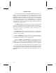
FREQUENTLY CALLED NUMBERS MEMORY LOCATION 01 02 03 04 05 06 07 08 09 10 11 12 13 14 15 16 17 18 19 20 21 22 23 24 25 26 27 28 29 30 31 32 33 34 35 36 37 38 39 40 41 42 43 44 45 46 47 48 49 50 54 NAME TELEPHONE NUMBER
WARRANTY A. Ericsson Inc. (hereinafter "Seller") warrants to the original purchaser for use (hereinafter "Buyer") that Equipment manufactured by Seller shall be free from defects in material, workmanship and title, and shall conform to its published specifications. With respect to any Equipment not manufactured by Seller (except for integral parts of Seller’s Equipment to which the warranties set forth above shall apply).
EMERGENCY NUMBERS Police State Police Fire Poison Control Ambulance Life Saving and Rescue Squad OPERATING TIPS The following conditions tend to reduce the effective range of two-way radios and should be avoided whenever possible. Operating the radio in low areas of terrain or while under power lines or bridges. Obstructions such as mountains or buildings between the vehicle sending and the system/person receiving the message.