LBI-38987B Configuration Manual EDACS Single Channel Autonomous Trunking (SCAT) GETC ericssonz
LBI-38987B REVISION HISTORY REVISION DATE REASON FOR CHANGE B May-96 Correct drawing on page 28. A Oct-95 Updated to replace existing SCAT software with Release 5 Station GETC and Station Turbo software, 349A9607G5 and 344A4414G5. Also replaces SCAT Downlink software with Release 5 Link GETC and Link Turbo software, 344A4895G5 and 350A1121G5. May-94 Original. NOTICE! This manual covers Ericsson and General Electric products manufactured and sold by Ericsson Inc.
LBI-38987B TABLE OF CONTENTS Section/Paragraph Page REVISION HISTORY.................................................................................................................................... 2 TABLE OF CONTENTS................................................................................................................................ 3 LIST OF FIGURES ........................................................................................................................................
LBI-38987B TABLE OF CONTENTS Section/Paragraph Page SCAT Downlink GETC ......................................................................................................................24 CLEAR VOICE CHECKOUT ...................................................................................................................24 Locally Initiated Calls .........................................................................................................................24 Multisite Initiated Calls.....
LBI-38987B LIST OF TABLES Table Title Page Table 1 - New Software Releases..........................................................................................................................7 Table 2 - EDACS Component Software Compatibility.........................................................................................9 Table 3 - Radio Compatibility...............................................................................................................................
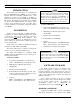
LBI-38987B INTRODUCTION NOTE INTRODUCTION This manual provides instructions for configuring the Ericsson GE Trunking Card (GETC) for use in a Single Channel Autonomous Trunking (SCAT) station. The information presented in this manual is applicable to EDACS SCAT stations using the MASTR II, IIe or MASTR III repeaters. The manual provides instructions for installing the SCAT Station GETC hardware and software, Turbo software, and programming the system’s personality.
SOFTWARE UPGRADES platform. As a result, it is no longer necessary to replace the Station GETC software with unique SCAT GETC software. Feature Enhancements The Release 5 GETC1e software adds SCAT Data, ProSound, Enhanced Multisite Login, and Voted Digital Interconnect (VDI) features. The SCAT operating mode will acquire many of these new features. These features are activated in the GETC personality using the GETC1e PC Programmer TQ-3357 V4.03 (with Field Macro “gtc_9505.mac”) or V5.0.
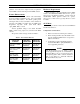
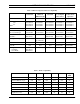
LBI-38987B RELATED PUBLICATIONS RELATED PUBLICATIONS It may be necessary to consult one or more of the following documents during the installation process. These manuals will also provide additional guidance if you encounter technical difficulties during the configuration process. SOFTWARE COMPATIBILITY EDACS COMPATIBILITY The data presented in Table 2 represents the minimum EDACS component software versions required to support the Release 5 software features.
SOFTWARE COMPATIBILITY LBI-38987B Table 2 - EDACS Component Software Compatibility EDACS COMPONENT Required for SCAT Data C3 MAESTRO IMC U58 U59 U3 N/A 344A3567G11 344A3568G11 344A3565G11 344A3630G11 MOM Site Controller N/A VAX System Manager PDP System Manager 344A4583G2 19A149495G8 Link GETC Link Turbo 344A4895G5 350A1121G5 PC Programmer TQ-3357 Ver 4.
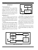
LBI-38987B OPERATION OPERATION SCAT GETC STAND-ALONE SCAT The stand-alone SCAT consists of a standard EDACS Station as shown in Figure 1, with the GETC personality configured for SCAT operation (special SCAT software 344A3835G2 required prior to release 5). In this configuration, the repeater transmits Control Channel information until a radio requests a channel. The SCAT repeater then assigns itself as the Working Channel and begins routing audio.
LBI-38987B Except for interconnect calls, all group and individual calls appear as transmission trunked calls to the radio and the CEC/IMC. This assures the mobile's quick return to the Control Channel. Local interconnect is unavailable on SCAT sites. However, use of the Centralized Telephone Interconnect System (CTIS or Jessica) is available in the multisite configuration. correction, general control of timer and IO functions (DIP switch, LED's, UART's, etc.
LBI-38987B CONFIGURATION CONFIGURATION The scat configuration process involves the following procedures and should be completed in the order presented: 1. Hardware Installation - The Hardware Installation procedure verifies proper installation of GETC hardware. 2. GETC Software Installation - The GETC Software Installation procedure provides instructions for installing the GETC operating software. 3.
CONFIGURATION operational. If you suspect that the GETC Logic board is not operating properly, refer to the Troubleshooting section in this manual. Upgrading Hardware GETC Shelves 19D901868G3 which are upgrading to the 349A9607G5 software must ensure their hardware is upgraded to the proper level. (The 19D901868G4 GETC Shelf meets all Release 5 requirements.) Turbo Board Installation This manual assumes the Turbo Board is previously installed and fully functional.
LBI-38987B CONFIGURATION Use the following procedure to install the modem if it is not already installed: 4. Verify the presence of demodulated signal data at TP107. 5. Adjust the transmit level potentiometer R2 for the maximum output level allowed by the phone line, microwave link, or equivalent communication line. For telephone lines linking the Station GETC to the CEC/IMC Uplink GETC, adjust R2 for .77 Vrms (0 dBm) measured across J6-8 and J6-9 (TB10-1 and 2).
TP109 TP107 TP110 TX Level Adj J3 R2 1 1 U19 S1 TP109 1 TP110 19D904266 1 1 J62 J68 J54 J11 TP107 J49 TP108 1 R2 1 Dip Switches S2 1 U3 J72 1 J29 S3 U4 U2 S4 TP108 J10 Reset Switch 1 1 J52 J27 J61 1 J12 1 1 1 J15 J9 1 U1 J67 1 J55 1 J44 U35 1 J8 J64 L1 1 J71 J18 L2 1 L3 J66 J65 J26 1 1 1 L4 1 1 J73 J69 1 L5 1 R1 LED Indicators 1 J63 1 J20 J14 J7 L6 R31 J21 1 1 J74 1 L7 1 1 1 J24 J28 TP104 1 J53 J19 T
LBI-38987B CONFIGURATION GETC SOFTWARE INSTALLATION 4. Ensure microprocessor U1 is the “Speedy” microprocessor 80C320 (RYT 121 6060/A). This processor is required when upgrading the software to 349A9607G5. The processor is available in the Speedy Upgrade Kit SPK9505. Replace if necessary. Refer to LBI-38894 for installation instructions. 5. Ensure Turbo Board harness has Ferrite Toroid installed. Toroid is included in the SPK9505 Speedy Upgrade Kit. Replace if necessary.
CONFIGURATION 1. Replace Group 5 GETC PROM with original software. 2. Reload original Programmer. Turbo software using PC 3. If changes were made to the personality, then reload the previous parameters. 4. The Speedy microprocessor upgrade, if installed, does not need to be reversed. If the original equipment was a GETC (GETC with no Turbo) platform, then perform the following steps:: 1. Replace Group 5 GETC PROM with original software. 2.
LBI-38987B CONFIGURATION TQ-3357 V4.03 (or later) 1. 2. Connect the TQ-3360 programming cable from the PC's serial port connector to the GETC Shelf connector J104 (A DB-25 to DB-9 adapter may be needed.) Using the TQ-3357’s LOAD utility, copy the Station Turbo software (344A4414) into the PC Programmer’s working directories. 3. Load the Field Macro “gtc_9505.mac” into the TQ-3357 PC Programmer using the instructions contained in Chapter 5 of the TQ-3357 manual. 4.
CONFIGURATION LBI-38987B NOTE PERSONALITY PROGRAMMING NOTE It is not necessary to recreate the personality when upgrading from 344A3835G2 software to 349A9607G5 except when upgrading non-turbo platforms. Personality refers to the system configuration data stored in the GETC's memory. The GETC's Personality includes system configuration information such as channel frequencies, call parameters, operating modes, and identification information.
LBI-38987B CONFIGURATION S1 1 2 3 4 5 S2 6 7 8 1 2 OPEN 3 4 5 S3 6 7 8 1 2 3 OPEN 4 5 6 7 8 Programming a Personality Using TQ-3357 Version 4.03 (or later) When using TQ-3357 Version 4.03 (or later), program the personality through J104. OPEN 1. Connect one end of the serial programming cable (TQ3360) to the computer. Connect the other end of the cable to the GETC Shelf connector J104. See Figure 9. 2.
CONFIGURATION LBI-38987B Table 6 - Sample Station Personality Personality: C:\GE\GTC\PERS\SCAT_PER.GTC ~~~~~~~~~~~~~~~~~~~~~~~~~~~~~~~~~~~~~~~~~~~~~~~~~~~~~~~~~~~~~~~~~~~~~~~~~~~~ Personality Description These are SCAT Site and SCAT Downlink Personalities. Centralized Telephone Interconnect System (CTIS) Option is enabled. Channel Allocations Channel Number 1234 56789 11111 11111 01234 56789 22222 22222 01234 56789 333 012 Control Channel Y... Clear Voice Y... Digital Voice .... Data ....
LBI-38987B CONFIGURATION Table 6 - Sample Station Personality (Continued) CONFIRMED CALL ENABLES STATUS: Clear Voice Digital Voice ----------------------Group Calls: No No Indiv Calls: No No Teleph Calls: No No Conventional Network Interface Data Digital Voice Group ID **GETC Personality Extended Options: ~~~~~~~~~~~~~~~~~~~~~~~~~~~~~~~~~~~~~~~~~ CV C-Call Timeout 0 DV C-Call Timeout 0 Wide Area DV No Data Mode RF Data Polarity Invert None Baud Rate 9600 Dig.Voted Inter.
CONFIGURATION 6. Read the existing personality from the SCAT Station GETC to the PC. If the personality does not exist, retrieve the sample SCAT Personality (shown in Table 6) from the PC. Change the personality parameters as required. NOTE NOTE LBI-38987B channel. As a TRACKED group, the SCAT channel only receives requests from the CEC/IMC for groups that are logged into the SCAT system.
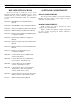
LBI-38987B OPERATIONAL CHECKOUT OPERATIONAL CHECKOUT Verify that the GETC is operating correctly by performing the following steps: DIP SWITCH SETTINGS The GETC DIP Switch settings depend on the GETC's usage (Station GETC or SCAT Downlink GETC), channel, and frequency. Through improvements in software and hardware, fewer changes in DIP switch settings are required.
OPERATIONAL CHECKOUT 7. Unkey the radio and verify that the station returns to the Control Channel mode. Multisite Initiated Calls 1. 2. LBI-38987B 2. Initiate a call from radio 1 to radio 2 using the Digital Voice mode. 3. When the call is received, verify that SCAT Station GETC LEDs L1, L6, and L7 turn ON (see Table 10). Initiate a multisite call or a console call to a radio assigned to the SCAT station.
LBI-38987B LED INDICATORS LED Indicators TROUBLESHOOTING Table 12 is a summary of the operating modes and the associated LED indications. The hardware used in the GETC is extremely reliable, making component failure the unlikely cause of most problems. The most common causes of problems are programming errors and interface connections. Table 12 - LED Indications, Summary LED Indicators L1 L2 L3 L4 L5 L6 L7 SCAT STATION GETC Control Channel ● ❍ ❍ ❍ ❍ ● CV Working Channel. Locally initiated call.
INTERCONNECT DIAGRAMS J100 To Site Controller (MSL) 1 6 2 7 3 8 4 9 5 J102 To Other GETCs (BSL) 1 6 2 7 3 8 4 9 5 19C336863G1 P8 J101 3 2 1 6 4 5 P1 9 1 6 2 7 3 8 4 9 5 4 6 3 2 1 3 2 1 6 4 5 19C320811 (MASTR II/IIe) 19B802401 (MASTR III) Lightning GETC 19D904266 J8 GND RxD TxD BSL RxD BSL TxD J19 4 GND 6 FSL 3 GND 2 RxD 1 TxD J3 J6 Delay PTT Phone Rx Phone Rx Phone Tx Phone Tx Det Dis (MIII) DATA (MII) CLK (MII) LOCK DET (MII) LD EN (MII) REM PTT OUT P6 1 6 7 8 9 10 11 12 13 15 13 J7 V
LBI-38987B INTERCONNECT DIAGRAM MASTR II (IIe) EDACS NETWORK SCAT INTERCONNECTION DIAGRAM 28
INTERCONNECT DIAGRAM LBI-38987B MASTR III EDACS NETWORK SCAT INTERCONNECTION DIAGRAM (188D5683, SH.1, REV.
LBI-38987B PARTS LIST GETC CABLE 19C336863G1 SYMBOL PART NUMBER DESCRIPTION ------------------- JACKS ------------------- J100 thru J102 19B209727P18 Connector: 9 contacts; sim to AMP 205203-1. ------------------- PLUGS -----------------P8 19A700041P32 Shell: 6-Position; sim to Molex 22-012065. P19 19A700041P32 Shell: 6-Position; sim to Molex 22-012065. ----------- MISCELLANEOUS ----------- 30 2 19B209727P11 Contact, electrical: sim to AMP 166504-0.
CABLE AND HARNESS DIAGRAMS LBI-38987B GETC CABLE 19C336863G1 (19C336863, Sh. 1, Rev. 4; 19C336866, Sh. 1, Rev.
LBI-38987B CABLE AND HARNESS DIAGRAM SCAT INTERCONNECT CABLE 19C337102G1 (19C337102, Sh. 1, Rev.
LBI-38987B This page intentionally left blank 33
LBI-38987B Ericsson Inc. Private Radio Systems Mountain View Road Lynchburg, VA 24502 1-800-528-7711 (Outside USA, 804-528-7711) Printed in U.S.A.