
Installation manual


LBI-38987B OPERATIONAL CHECKOUT
24
OPERATIONAL CHECKOUT
Verify that the GETC is operating correctly by
performing the following steps:
DIP SWITCH SETTINGS
The GETC DIP Switch settings depend on the GETC's
usage (Station GETC or SCAT Downlink GETC), channel,
and frequency.
Through improvements in software and hardware, fewer
changes in DIP switch settings are required. As a result
more switch positions are being ignored and their
functionality is being programmed into the GETC via the
Personality Programming.
Set the GETC DIP switches using the following
procedures:
SCAT Station GETC
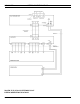
Set the three GETC DIP switches (S1 - S3) for SCAT
Station operation, as shown in Figure 8.
1. Set S1-1 thru S1-7 and S2-1 thru S2-4 to the repeater's
operating frequency. Refer to Station GETC manual
LBI-38988 or SRN1060 for DIP switch settings.
NOTE
For MASTR II/IIe (using 349A9607G5 or later)
and MASTR III stations, set DIP switches S1-1
through S1-7 and S2-1 through S2-4 to the
CLOSED position. Frequency is selected via the
Personality programming.
2. Set S1-8 to the OPEN position.
3. Set S2-5, 6 and 8 to CLOSED and S2-7 to the OPEN
position.
4. Set S3-1 to OPEN and S3-2 thru S3-5 to CLOSED.
This sets the SCAT Station GETC for operation on
channel number 1.
5. Set S3-6 and S3-8 to OPEN and S3-7 to CLOSED.
SCAT Downlink GETC
Set the three GETC DIP switches (S1 - S3) for SCAT
Downlink operation. Refer to the Link GETC Configuration
manual, LBI-38896, and SRN1061 for instructions.
CLEAR VOICE CHECKOUT
The following tests allow you to confirm the SCAT
Station GETC operation when the GETC operates as a
Control Channel GETC and when making Clear Voice (CV)
calls
Locally Initiated Calls
This procedure assumes that the test radios being used
have their personalities programmed to enable SCAT, set to
the SCAT group frequency, and operating in Clear Voice
mode.
1. Apply power to the station (or reset the GETCs). The
station should default to the Control Channel mode.
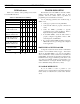
2. Verify the SCAT and SCAT Downlink GETC LEDs
when the station is in the Control Channel mode (see
Table 7).
•
SCAT Station GETC - L1, L6, and L7 turn ON.
Table 7 - SCAT Station GETC, CC Mode
LED Indicators L1 L2 L3 L4 L5 L6 L7
Control Channel
(Idle Mode)
●❍❍❍❍●●
Legend:
❍
= OFF
●
= ON
❉
= FLASHING
3. Set test radios 1 and 2 to group 1.
4. Initiate a call from radio 1 to radio 2.
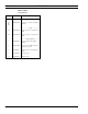
5. Verify that the SCAT Station GETC switches from the
Control Channel mode to the Working Channel mode as
shown in Table 8 (LED L7 goes OFF).
Table 8 - LED Indications, Clear Voice Local Call
LED Indicators L1 L2 L3 L4 L5 L6 L7
CV Working Channel
●❍❍❍❍●❍
Legend:
❍
= OFF
●
= ON
❉
= FLASHING
6. Verify that voice can be heard on both radios and that
the ID of the transmitting radio is displayed on the
receive radio.
Figure 10 - Typical SCAT Station DIP Switch Settings
NOTE