
Installation manual


LBI-38987B LED INDICATORS
26
LED Indicators
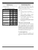
Table 12 is a summary of the operating modes and the
associated LED indications.
Table 12 - LED Indications, Summary
LED Indicators L1 L2 L3 L4 L5 L6 L7
SCAT STATION GETC
Control Channel
●❍❍❍❍●●
CV Working Channel.
Locally initiated call.
●❍❍❍❍●❍
CV Working Channel.
Multisite initiated call.
●●❍❍❍●❍
DV Working Channel.
Locally initiated call.
●❍❍❍❍●●
DV Working Channel
Multisite initiated call.
●●❍❍❍●●
Downlink GETC
Downlink.
●●❍❍❉❉❍
Legend:
❍
= OFF
●
= ON
❉
= FLASHING
TROUBLESHOOTING
The hardware used in the GETC is extremely reliable,
making component failure the unlikely cause of most
problems. The most common causes of problems are
programming errors and interface connections.
Use the following guidelines when troubleshooting a
GETC on site:
1. Verify proper operation of front panel LEDs.
2. Verify that all cables are properly connected and
secure.
3. Verify the GETC’s personality is properly
programmed for the specific application. Refer to
TQ-3357, PC Programmer and SRN1061.
4. In Downlink GETCs, verify the Turbo Board is
properly configured if applicable. Refer to LBI-
38822, TQ-3357, and SRN 1061.
5. If you suspect that the GETC has failed, replace the
GETC with a known good unit properly configured
for this application.
DOWNLINK ACTIVITY LOGGER
A diagnostic feature introduced with the 344A4895G4
software is the Downlink Activity Logger. This feature
allows the Downlink GETC to log and save information
about communication activity between the Downlink and
Uplink GETC. In General, the information supplied by the
Downlink Activity Logger is EDACS specific and in some
cases may need technical assistance for interpretation. For
detailed instructions on using the Channel Activity Logger,
refer to SRN1061 and TQ 3357 V4.03 (or later).
IN CASE OF DIFFICULTY
If you are unable to resolve a problem to your
satisfaction, then contact the Ericsson Technical Assistance
Center (TAC) at 1-800-528-7711 (outside USA, 804-528-
7711).