
Installation manual

LBI-38988
11
CONFIGURATION
The configuration process involves the following
procedures and should be completed in the order presented:
1. Hardware Installation - The Hardware Installation
procedure verifies proper installation of GETC
hardware.
2. Firmware Installation - The Firmware Installation
procedure provides instructions for installing the
GETC operating firmware.
3. Software Installation - The Software Installation
procedure provides instructions for installing the
Turbo Board software.
4. Personality Programming - This step provides
instructions for programming and storing system
configuration data in the GETC.
5. Operational Checkout - The Operational Checkout
procedure provides instructions for verifying the
GETC operation when the configuration is
complete.
HARDWARE INSTALLATION
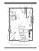
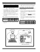
Typically, a Station GETC is installed in an EDACS
station cabinet just above each of the station's radio
assemblies as shown in Figure 2. The assembly is mounted
within a slide out shelf measuring 1.75 inches high (one rack
unit) by 19 inches wide.
Installation or removal of the shelf sub-assemblies
involves sliding the GETC shelf out of the cabinet and into
the service position. This position allows access to the
shelf's sub-assemblies. Install all components with the
appropriate screws, nuts, and washer hardware. Refer to the
MASTR IIe (LBI-38430) or MASTR III (LBI-38636)
Application Assembly Diagrams for detailed information on
installing the GETC Shelf.
Observe basic safety precautions to prevent injury or
equipment damage.
GETC Logic Board Installation
This manual assumes the GETC Logic Board
(19D904266G1 or G4) is previously installed, setup for the
default configuration (Wideband EDACS Station), and fully
operational. If for any reason the GETC Logic board is
suspect, refer to LBI-38894 for detailed instructions for
removing, replacing, and testing the GETC Logic Board or
the Regulator Board.
Turbo Board Installation
This manual assumes the Turbo Board is previously
installed and fully functional. If, after installing or
attempting to install the Turbo Software, the Turbo Board is
suspect refer to LBI-38822 and SRN-1060 or 1062 for
detailed instructions for removing, replacing, and testing the
Turbo Board.
Rockwell Modem Installation
The Rockwell Modem provides a high speed
synchronous serial interface between the Station GETC and
the CEC/IMC's Uplink GETC. The Station GETC uses the
modem to send and receive serial digital data representing
GID information, polling messages, keying messages, and
channel assignments. Data transfer rates are 9600 bits per
second (bps) using dedicated 3002 data grade four-wire
audio lines. Technical specifications for the modem may be
found in LBI-33031. Information on installing and testing
the modem may be found in LBI-38894, and LBI-38822.
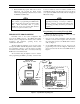
Modem Alignment
Use the following steps to set up the basic audio line
levels. If the Station GETC is linked to a multisite system
other than the CEC/IMC (i.e. Data Gateway), different
levels may be required. Consult the applicable system
installation manual for the required levels.
1. Ensure jumpers are installed on J11 pins 1 & 2 and
J12 pins 1 & 2.
2. Apply power to the GETC.
CABINET
REPEATER
CHANNEL #5
REPEATER
SPACE
STATION GETC
POWER SUPPLYPOWER SUPPLY
STATION GETC
SPACE
REPEATER
CHANNEL #3
CHANNEL #4
REPEATER
STATION GETC
SPACE
POWER SUPPLY
REPEATER
CABINET
POWER SUPPLY
STATION GETC
SPACE
REPEATER
CHANNEL #1
CHANNEL #2
REPEATER
STATION GETC
SPACE
POWER SUPPLY
REPEATER
CABINET
DISTRIBUTION
PANEL
DISTRIBUTION
PANEL
DISTRIBUTION
PANEL
Figure 2 - Typical Five Channel Repeater
Cabinet