
Installation manual

LBI-38988
12
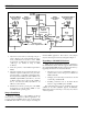
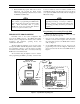
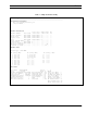
3. Adjust the receive level by monitoring U18 pin 1
(refer to Figures 3 and 4) and adjusting the receive
level potentiometer R1 (located on the GETC
Logic Board) for 400 mVpp as measured with an
oscilloscope (85 mVrms if using an RMS
Voltmeter).
4. Verify the presence of demodulated signal data at
TP107.
5. Adjust the transmit level potentiometer R2 for the
maximum output level allowed by the phone line,
microwave link, or equivalent communication line.
For telephone lines linking the Station GETC to the
CEC/IMC Uplink GETC, adjust R2 for .77 Vrms
(0 dBm) measured across J6-8 and J6-9 (TB10-1
and 2). For microwave links, adjust R2 for -10
dBm across J6-8 and J6-9.
6. Initialize the modem by pressing S4 (on the GETC
Logic Board) to reset the Station GETC or cycle
the GETC Shelf's operating power.
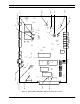
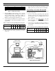
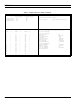
Jumper Installation
There are a few jumpers on the GETC Logic Board
which must be re-configured for different applications. To
properly configure the GETC jumpers, refer to jumper tables
in SRN1060 and install or remove jumpers according the
intended GETC application. The location of the jumpers
may be found using the board layout diagram in Figure 4.
Upgrading to 344A9607G4 Software
GETC Shelves 19D901868G3 which are upgrading to
the 344A9607G4 software must also upgrade their hardware
(the 19D901868G4 GETC Shelf is upgraded at the factory).
Upgrading the hardware involves three elements:
• The microprocessor U1, 19A705557P1 (80C32), is
replaced with a faster microprocessor RYT 121
6060/A (80C320).
• Changing the modem chips U4 and U19 to the TI
modem chips 19A704727P4.
• Installing a Ferrite Toroid on the Turbo Board
harness to suppress EMI spurs at 74 MHz.
The replacement microprocessor and Ferrite Toroid are
available in the field installable upgrade kit SPK9505.
Replacement of the modem chips is necessary, they must be
ordered separately.
68
1
2
52
12
5
T1
J6-07
Telephone Line
J6-06
J67
R36
604
D11 D10
R1
5K
2
3
1
U18A
4558
J11
Demodulated
Rx Data
TP107
Rockwell
Modem
19A705178
J3C-22
J3A-32
J3C-24
J3A-31
R2
1K
R38
220
7
6
U18B
4558
D13 D12
R146
604
68
52
T2
Unmodulated
Tx Data
TP105
J6-09 J6-08
Telephone Line
Level Adjustments
D0
4
D1
5
D2
6
D3
7
D4
8
D5
9
D6
10
D7
11
19 21
U19
Rx Tx
Serial Data
Parallel
Data Bus
Receiving Half of
Telephone Line
Transmitting Half of
Rx
Level
Tx
Level
Figure 3 - GETC Phone Line Level Adjustments