
Installation manual


LBI-38988
22
1. Verify the GETC LED indicators for the Failsoft
Control Channel and idle Working Channels are correct as
shown in Table 6.
Table 6 - LED Indicators for Failsoft Idle Channels
LED Indicators L1 L2 L3 L4 L5 L6 L7
Failsoft Idle WB
Working Channel
●❍❍❍❍❍●
Failsoft WB Control
Channel
●❍❍❍❍●●
Failsoft Idle NB
Working Channel
●❍●❍❍❍●
Failsoft NB Control
Channel
●❍●❍❍●●
Legend:
❍
= OFF
●
= ON
❉
= FLASHING
NOTE
To switch a GETC from the Control Channel
operation to Working Channel operation, press and
hold S4 on the Control Channel GETC. This
causes the Failsoft System to re-assign the Control
Channel responsibilities to the next functioning
GETC. Release S4 and verify LEDs.
2. Place Clear Voice calls on both wideband or
narrowband channels and Digital Voice calls on the
wideband channels to verify correct operation.
3. Verify LED indicators are correct, as shown in
Table 7, for the Failsoft Wideband channel(s)
assigned Clear Voice and Digital Voice calls and
Failsoft Narrow Band channel(s) assigned Clear
Voice calls.
4. Repeat for all channels.
Table 7 - LED Indicators for Failsoft Assigned
Channels
LED Indicators L1 L2 L3 L4 L5 L6 L7
Failsoft Assigned WB
Clear Call
●❍❍❍❍●❍
Failsoft Assigned WB
Digital Voice Call
●❍❍❍❍●❍
Failsoft Assigned NB
Clear Call
●❍●❍❍●●
Legend:
❍
= OFF
●
= ON
❉
= FLASHING
Satellite Site Receiver
Verify proper operation of a GETC used in as a
Satellite Site Receiver by observing the GETC LED
indicators when the receiver is used as a Control Channel
and idle or assigned Working Channel as shown in Table 8.
Table 8 - LED Indicators for Satellite Site Receivers
LED Indicators L1 L2 L3 L4 L5 L6 L7
WB Working Channel
Satellite Site Idle
●❍❍❍❍❍●
WB Working Channel
Satellite Site Assigned
●❍❍❍❍●●
WB Control Channel
Satellite Site
●●❍❍❍❍●
Legend:
❍
= OFF
●
= ON
❉
= FLASHING
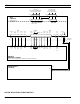
INTERFACE SIGNALS
Table 10 describes the various interface signals between
the GETC and the Station Repeater. For the specific
location of these signals, refer to the Interconnect Diagrams.
NOTE