LBI-38988B Configuration Manual EDACS Station GETC1e 19D901868G3 and G4 ericssonz
LBI-38988 REVISION HISTORY REVISION DATE REASON FOR CHANGE B Sep-95 Updated to include Station GETC1e Release 5 software, 349A9607G5 and Turbo Board software, 344A4414G5. A Jan-95 Updated to include Station GETC1e Release 4 software, 349A9607G4 and instructions for using PC Programmer TQ-3357 V4.03. Jul-94 Original NOTICE! This manual covers Ericsson and General Electric products manufactured and sold by Ericsson Inc.
LBI-38988 TABLE OF CONTENTS Page REVISION HISTORY..............................................................................................................................2 INTRODUCTION.....................................................................................................................................6 SOFTWARE FEATURES ........................................................................................................................6 349A9607G5 SOFTWARE ...........................
LBI-38988 TABLE OF CONTENTS Page DIP Switch Settings ...................................................................................................................... 26 Fully Trunked System ................................................................................................................... 26 Failsoft System.............................................................................................................................. 27 Satellite Site Receiver ...........................
LBI-38988 LIST OF TABLES Page Table 1 - GETC EPROM and Turbo Software Compatibility ...............................................9 Table 2 - EDACS Component Software Compatibility.........................................................10 Table 3 - Radio Compatibility..............................................................................................10 Table 4 - GETC Hardware Compatibility.............................................................................
LBI-38988 INTRODUCTION INTRODUCTION This manual provides instructions for configuring the Ericsson GE Trunking Card Shelf (GETC), part number 19D901868G3 and G4, for Station (including repeater and SCAT), Satellite Site Receiver, and VDI Control operation. This manual is applicable to GETC (pronounced “getsee”) hardware platforms installed in wideband or narrow band 800 MHz, 900 MHz, UHF, and VHF stations.
SOFTWARE FEATURES • • • • • • • • Receive Adjacency information from the Site Controller or Downlink. 1. A particular site color is programmed in the Control Channel GETC. Count the number of actual Adjacent Systems listed in the Adjacency Message. 2. The outbound Control Channel messaging tells the radio which “color” to use on inbound transmissions. Build an Adjacencies Table Length Definition Message and send it. 3.
LBI-38988 SOFTWARE FEATURES capability of listening to both the IMC and the Voter simultaneously. For a Simulcast system, no additional equipment is required once the system is equipped for Digital Dispatch. A wiring modification is made to the digital path between the Voter Selector and the Control Point GETC to provide a continuous data path between them. The modification gives the Control Point GETC the capability of listening to both IMC and the Voter Simultaneously.
RELATED PUBLICATIONS RELATED PUBLICATIONS It may be necessary to consult one or more of the following documents during the installation process. These manuals will also provide additional guidance if you encounter technical difficulties during the configuration process. LBI-38430 - MASTR IIe Control Shelf Maintenance Manual. LBI-38636 - MASTR III Base Station Installation Manual. LBI-38822 - Turbo Board (GETC-1e) Maintenance Manual. LBI-38894 - GETC Trunking Card Maintenance Manual.
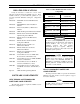
LBI-38988 SOFTWARE COMPATIBILITY RADIO COMPATIBILITY Table 3 describes the minimum software requirements for radio products supporting the features included in this release. Table 2 - EDACS Component Software Compatibility EDACS COMPONENT Required for SCAT Data C3 MAESTRO IMC N/A 344A3567G11 344A3568G11 344A3565G11 344A3630G11 U58 U59 U3 MOM Site Controller N/A VAX System Manager PDP System Manager 344A4583G2 19A149495G8 Link GETC Link Turbo 344A4895G5 350A1121G5 PC Programmer TQ-3357 Ver 4.
HARDWARE COMPATIBILITY NOTE HARDWARE COMPATIBILITY NOTE The GETC hardware compatibility depends on the version of EPROM installed on the Logic Board, refer to the following table: Table 4 - GETC Hardware Compatibility GETC LOGIC BOARD EPROM, U2 LOGIC BOARD TURBO BOARD 349A9607G5 19D904266G4 19D904266G1 19D903536P1 349A9607G4 19D904266G4 19D904266G1 19D903536P1 349A9607G3 19D904266G1 19D903536P1 349A9607G2 (or earlier) 19D904266G1 19D903536P1 19A705595G8 19D904266G1 19D903536P1 LBI-38988
LBI-38988 DESCRIPTION DESCRIPTION The Station GETC is the foundation of all EDACS trunking operations. It is capable of operating in the Trunked Failsoft mode or as part of a fully trunked system or network. In the Trunked Failsoft mode, one of the Station GETCs operates as the Control Channel GETC, providing the command and control link between the mobile radios and the EDACS system.
LBI-38988 whenever the communications between the Site Controller and the Control Channel GETC is lost. TX MOD (J7-4) Direct modulation input to the synthesizer-exciter (MIIe only). GETC DATA (J7-5) Input to the transmitter for filtered High Speed Data (HSD) to be transmitted. VOL\SQ HI (J7-2) Unfiltered receiver audio (9600 or 4800 baud data, voice, or Low Speed Data (LSD). LSD TX (J19-5) Low-Speed Data to be transmitted.
LBI-38988 CONFIGURATION CONFIGURATION The configuration process involves the following procedures and should be completed in the order presented: 1. Hardware Installation - The Hardware Installation procedure verifies proper installation of GETC hardware. 2. GETC Software Installation - The GETC Software Installation procedure provides instructions for installing the GETC operating software, 349A9607. 3.
CONFIGURATION Parallel Data Bus Receiving Half of Telephone Line J6-07 J6-06 8 T1 D0 D1 D2 D3 D4 D5 D6 D7 TP105 Unmodulated Tx Data U19 6 Serial Data 19 Rx 5 R36 604 TP107 Demodulated Rx Data 4 5 6 7 8 9 10 11 LBI-38988 Transmitting Half of Telephone Line J6-09 J6-08 2 5 1 2 J11 1 2 J67 D11 8 T2 Tx 21 D10 R1 5K Rx Level U18A 4558 2 1 3 Rockwell Modem 19A705178 J3C-22 J3C-24 J3A-32 J3A-31 R2 1K Telephone Line Level Adjustments Tx Level 6 2 R146 604 U18B 4558 5 7 6 D13 D12 R
TP109 TP107 TP110 J3 R2 TX Level Adj 1 1 U19 S1 TP109 1 TP110 19D904266 1 1 J62 J68 J54 J11 TP107 J49 TP108 1 R2 1 Dip Switches S2 1 U3 J72 1 J29 S3 U4 U2 S4 TP108 J10 Reset Switch 1 1 J52 J27 J61 1 J12 1 1 1 J15 J9 1 U1 J67 1 J8 U35 1 J55 1 J44 J64 L1 1 J71 J18 L2 1 L3 L4 1 J66 J73 1 L5 1 R1 J69 1 1 J65 J26 1 1 LED Indicators 1 J63 1 J20 J14 J7 L6 R31 J21 1 1 J74 1 L7 T2 1 1 J24 J28 TP104 1 J53 J19
CONFIGURATION LBI-38988 GETC SOFTWARE INSTALLATION 2. The GETC software installation procedure involves installing the latest version of the EPROM containing the GETC operating software. If upgrading from 19A149256G21 (or earlier) software, remove RAM chip U3 and install Turbo Board. Refer to LBI-38822 for instructions. 3. Ensure Modem chips U4 and U19 are TI AMPS modems 19A704272P4. TI Amps modems are required when upgrading to 349A9607G4 (or later), replace if necessary. 4.
LBI-38988 CONFIGURATION Replace if necessary. Refer to LBI-38894 for installation instructions. this manual and the detailed instructions contained in TQ-3357 and SRN1060. 15. Perform an operational checkout using the Failsoft System checkout procedures. 7. Ensure Turbo Board harness has Ferrite Toroid installed. Toroid is included in the SPK9505 Speedy Upgrade Kit. Replace if necessary. Refer to LBI-38822 for installation instructions. 8. Remove the Logic Board. 9.
CONFIGURATION Speedy Upgrade Kit. Replace if necessary. Refer to LBI-38822 for installation instructions. Satellite Receivers & Simulcast Remote TX Perform the following steps when installing the software in a GETC connected in a Voted system as a Satellite Site Receiver or at the Remote TX Site. NOTE NOTE For Voted systems using Satellite Site Receiver software, the Satellite Site Receiver software must be the same version as the Main/Control Site software before the channel will operate properly.
LBI-38988 CONFIGURATION De-installing The GETC-1e Software If a problem arises while upgrading or installing the new software, it may be necessary to de-install the software. Restoring the site to its original configuration will depend on which of the following the original hardware platform. The two cases are described below. If the original equipment configuration was a GETC1e (GETC with Turbo) platform, then perform the following steps: 1. Replace Group 5 GETC PROM with original software. 2.
CONFIGURATION NOTE NOTE PC Programmer Setup Prepare the PC for programming the GETC Turbo Board by performing the following steps: TQ-3357 V4.03 (or later) 1. Connect the TQ-3360 programming cable from the PC's serial port connector to the GETC Shelf connector J104 (A DB-25 to DB-9 adapter may be needed.) 2. Using the TQ-3357’s LOAD utility, copy the Station Turbo software (344A4414) into the PC Programmer’s working directories. 3. Load the Field Macro “gtc_9505.
LBI-38988 CONFIGURATION of the serial cable to the GETC Shelf connector J100, see Figure 5. S1 1 2. 3. 4. Set the GETC DIP switches S1, S2, and S3 for the programming mode as shown in Figure 6. Set S28, S3-3 and S3-6 to OPEN. All other S3 positions should be CLOSED. Switches S1-1 thru S2-7 can be in any position and need not be changed. DIP switches S1-S3 are located near the front of the GETC Shelf, see Figure 4.
CONFIGURATION 3. Verify that front panel LEDs L6 and L7 are flashing, as shown in Table 6. This indicates the GETC is ready for programming. 4. Proceed with the Personality programming as described in TQ-3357. 5. After saving the personality and downloading it into the GETC, perform an operational checkout of the GETC.
LBI-38988 CONFIGURATION Table 7 - Sample Station Personality Personality: C:\GE\GTC\PERS\SAMPLE.GTC ~~~~~~~~~~~~~~~~~~~~~~~~~~~~~~~~~~~~~~~~~~~~~~~~~~~~~~~~~~~~~~~~~~~~~~~~~~~~ Personality Description This is a sample personality for a Station GETC. Channel Allocations Channel Number 1234 56789 Control Channel YYYY Clear Voice YYYY Digital Voice YYYY Data YYYY Pager (DnLink GETC).... Interconnect YYYY Allow DV Telephone YYYY Multisite Downlink .... Downlink (to TSIN) .... YYYYY YYYYY YYYYY YYYYY YY...
CONFIGURATION LBI-38988 Table 7 - Sample Station Personality (Continued) CONFIRMED CALL ENABLES STATUS: Clear Voice Digital Voice ----------------------Group Calls: No No Indiv Calls: No No Teleph Calls: No No Conventional Network Interface Data Digital Voice Group ID **GETC Personality Extended Options: ~~~~~~~~~~~~~~~~~~~~~~~~~~~~~~~~~~~~~~~~~ CV C-Call Timeout 0 DV C-Call Timeout 0 Wide Area DV No Data Mode RF Data Polarity Invert None Baud Rate 9600 Dig.Voted Inter.
LBI-38988 OPERATIONAL CHECKOUT OPERATIONAL CHECKOUT 6. Set S3-1 thru S3-5 to the Channel Address. Refer to Table 8. Verify that the GETC is operating correctly by performing the following steps: 7. Set S3-6 to CLOSED. DIP Switch Settings 8. Set S3-7 OPEN for Simulcast or CLOSED for non-Simulcast. With software 349A9607G4 (or later) set S2-6 to CLOSED, use Personality Programming. 9. Set S3-8 to OPEN.
OPERATIONAL CHECKOUT 2. Place test calls from radios in Channel Test by keying one of the test radios and monitoring the audio from the other radio. Place Clear Voice calls and if programmed, Digital Voice calls. Table 9 - LED Indicators for Trunked Idle Channels LED Indicators ❍ ❍ ❍ ❍ ❍ ❍ ● Fully Trunked Idle NB Working Channel ❍ ❍ ● ❍ ❍ ❍ ● Fully Trunked WB Control Channel ❍ ❍ ❍ ❍ ❍ ● ● Fully Trunked NB Control Channel ❍ ❍ ● ❍ ❍ ● ● Legend: 3.
LBI-38988 OPERATIONAL CHECKOUT Table 12 - LED Indicators for Failsoft Assigned Channels Table 13 - LED Indicators for Satellite Site Receivers LED Indicators LED Indicators L1 L2 L3 L4 L5 L6 L7 L1 L2 L3 L4 L5 L6 L7 ● ❍ ❍ ❍ ❍ ● ❍ WB Working Channel Satellite Site Idle ● ❍ ❍ ❍ ❍ ❍ ● Failsoft Assigned WB Clear Call ● ❍ ❍ ❍ ❍ ● ● WB Working Channel Satellite Site Assigned ● ❍ ❍ ❍ ❍ ● ● Failsoft Assigned WB Digital Voice Call ● ❍ ● ❍ ❍ ● ❍ WB Control Channel Satellite Site ● ● ❍ ❍ ❍ ❍ ● Failsoft
TROUBLESHOOTING TROUBLESHOOTING The hardware used in the GETC is extremely reliable, making component failure the unlikely cause of most problems. The most common causes of problems are programming errors and interface connections. Use the following guidelines when troubleshooting a GETC on site: 1. Verify the operation of front panel LEDs. This can be done by performing the Operational Checkout and verifying the LED indications.
LBI-38988 TROUBLESHOOTING Table 15 - Interface Status During Various States SIGNAL STATE STATUS Control Channel: Vol/Sq (J7-2) Data High Speed signaling is being routed to the HSD Detector. RUS In (J7-14) High Receiver is unsquelched and watching carrier activity for the presence (present = Low) of an interfering signal (without valid signaling). Rus Out (J7-15) Low GETC is receiving HSD and mutes the receiver (no Receiver audio to the transmitter).
TROUBLESHOOTING LBI-38988 Table 15 - Interface Status During Various States (Continued) SIGNAL STATE STATUS Working Channel (Active): Handshake Mode Vol/Sq (J7-2) Data Listening to High Speed handshake. RUS In (J7-14) N/A RUS activity is being ignored during the handshake. Rus Out (J7-15) L/H Receiver is muted (no receiver audio to the transmitter) until call is validated. RPT Inhibit (1950 DIS) (J6-5) Low If a Voting system, this line is low during a Control Channel.
LBI-38988 TROUBLESHOOTING Table 15 - Interface Status During Various States (Continued) SIGNAL STATE STATUS Working Channel (Active): During Digital Call Vol/Sq (J7-2) Analog Digital Voice data on this line. RUS In (J7-14) N/A Carrier activity is ignored during Digital Voice call. Rus Out (J7-15) Low Receiver is muted. RPT Inhibit (1950 DIS) (J6-5) Low If a Voting system, this line is low during a Digital Voice call. The 1950 Hz tone is present on the Line Output.
INTERCONNECT DIAGRAMS J100 To Site Controller (MSL) 1 6 2 7 3 8 4 9 5 J102 To Other GETCs (BSL) 1 6 2 7 3 8 4 9 5 19C336863G1 P8 J101 3 2 1 6 4 5 P1 9 1 6 2 7 3 8 4 9 5 4 6 3 2 1 3 2 1 6 4 5 19C320811 (MASTR II/IIe) 19B802401 (MASTR III) Lightning GETC 19D904266 J8 GND RxD TxD BSL RxD BSL TxD J19 4 GND 6 FSL 3 GND 2 RxD 1 TxD J3 J6 Delay PTT Phone Rx Phone Rx Phone Tx Phone Tx Det Dis (MIII) DATA (MII) CLK (MII) LOCK DET (MII) LD EN (MII) REM PTT OUT P6 1 6 7 8 9 10 11 12 13 15 13 J7 V
LBI-38988B INTERCONNECT DIAGRAMS MASTR III STATION INTERCONNECT 34 Rev.
LBI-38988 Serial Link to Site Controller, Downlink GETC, and other Station GETC's J100 3 2 P8 1 2 3 J8 1 2 3 GETC 19D901868 GETC Logic Board 19D904266 RX DATA RUS IN RUS OUT 2 4 9 14 15 J6 1 67 89 11 15 P26 1 67 89 11 2 4 9 14 2 6 P19 6 4 6 J19 6 4 MODEM Data REM PTT IN P27 3 1 SYNC GND TX GND BSL DATA TX MOD J7 J102 1 VOL/SQ HI Delay PTT Failsoft GETC Data to Downlink GETC and other Station GETC's LOCK DET LD EN REM PTT OUT 12 13 15 16 J19 5
LBI-38988B GETC CABLE 19C336863G1 SYMBOL PART NUMBER DESCRIPTION ------------------ JACKS -----------------J100 thru J102 19B209727P18 Connector: 9 contacts; sim to AMP 205203-1. P8 19A700041P32 Shell: 6-Position; sim to Molex 22-012065. P19 19A700041P32 Shell: 6-Position; sim to Molex 22-012065. ----------------- PLUGS ----------------- --------------- MISCELLANEOUS---------------- 2 19B209727P11 Contact, electrical: sim to AMP 166504-0.
LBI-38988 GETC CABLE 19C336863G1 (19C336863, Sh. 1, Rev. 4; 19C336866, Sh. 1, Rev. 0) Rev.
LBI-38988B This page intentionally left blank 38 Rev.
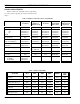
800 MHZ FREQUENCY SELECTIONS LBI-38988 APPENDIX A 800 MHZ EDACS APPLICATIONS FREQUENCY SELECTIONS GETC DIP SWITCH SETTINGS NOTE NOTE For MASTR II/IIe using Station GETC software 349A9607G4 (or earlier) only. For MASTR II, IIe, and III using 349A9607G5 (or later), set switches S1-1 thru S1-7 and S2-1 thru S2-4 to the CLOSED position Rev.
LBI-38988 TX FREQ (MHz) 800 MHZ FREQUENCY SELECTIONS S1-1 Thru S1-7 S2-1 Thru S2-4 851 MHz 851.0125 851.0250 851.0375 851.0500 851.0625 851.0750 851.0875 851.1000 851.1125 851.1250 851.1375 851.1500 851.1625 851.1750 851.1875 851.2000 851.2125 851.2250 851.2375 851.2500 851.2625 851.2750 851.2875 851.3000 851.3125 851.3250 851.3375 851.3500 851.3625 851.3750 851.3875 851.4000 851.4125 851.4250 851.4375 851.4500 851.4625 851.4750 851.4875 851.
800 MHZ FREQUENCY SELECTIONS TX FREQ (MHz) 852.4875 852.5000 852.5125 852.5250 852.5375 852.5500 852.5625 852.5750 852.5875 852.6000 852.6125 852.6250 852.6375 852.6500 852.6625 852.6750 852.6875 852.7000 852.7125 852.7250 852.7375 852.7500 852.7625 852.7750 852.7875 852.8000 852.8125 852.8250 852.8375 852.8500 852.8625 852.8750 852.8875 852.9000 852.9125 852.9250 852.9375 852.9500 852.9625 852.
LBI-38988 TX FREQ (MHz) 800 MHZ FREQUENCY SELECTIONS S1-1 Thru S1-7 S2-1 Thru S2-4 854 MHz 854.0000 854.0125 854.0250 854.0375 854.0500 854.0625 854.0750 854.0875 854.1000 854.1125 854.1250 854.1375 854.1500 854.1625 854.1750 854.1875 854.2000 854.2125 854.2250 854.2375 854.2500 854.2625 854.2750 854.2875 854.3000 854.3125 854.3250 854.3375 854.3500 854.3625 854.3750 854.3875 854.4000 854.4125 854.4250 854.4375 854.4500 854.4625 854.4750 854.
800 MHZ FREQUENCY SELECTIONS TX FREQ (MHz) S1-1 Thru S1-7 S2-1 Thru S2-4 855.5000 855.5125 855.5250 855.5375 855.5500 855.5625 855.5750 855.5875 855.6000 855.6125 855.6250 855.6375 855.6500 855.6625 855.6750 855.6875 855.7000 855.7125 855.7250 855.7375 855.7500 855.7625 855.7750 855.7875 855.8000 855.8125 855.8250 855.8375 855.8500 855.8625 855.8750 855.8875 855.9000 855.9125 855.9250 855.9375 855.9500 855.9625 855.9750 855.
LBI-38988 TX FREQ (MHz) 800 MHZ FREQUENCY SELECTIONS S1-1 Thru S1-7 S2-1 Thru S2-4 857 MHz 857.0000 857.0125 857.0250 857.0375 857.0500 857.0625 857.0750 857.0875 857.1000 857.1125 857.1250 857.1375 857.1500 857.1625 857.1750 857.1875 857.2000 857.2125 857.2250 857.2375 857.2500 857.2625 857.2750 857.2875 857.3000 857.3125 857.3250 857.3375 857.3500 857.3625 857.3750 857.3875 857.4000 857.4125 857.4250 857.4375 857.4500 857.4625 857.4750 857.
800 MHZ FREQUENCY SELECTIONS TX FREQ (MHz) S1-1 Thru S1-7 S2-1 Thru S2-4 858.5000 858.5125 858.5250 858.5375 858.5500 858.5625 858.5750 858.5875 858.6000 858.6125 858.6250 858.6375 858.6500 858.6625 858.6750 858.6875 858.7000 858.7125 858.7250 858.7375 858.7500 858.7625 858.7750 858.7875 858.8000 858.8125 858.8250 858.8375 858.8500 858.8625 858.8750 858.8875 858.9000 858.9125 858.9250 858.9375 858.9500 858.9625 858.9750 858.
LBI-38988 TX FREQ (MHz) 800 MHZ FREQUENCY SELECTIONS S1-1 Thru S1-7 S2-1 Thru S2-4 860 MHz 860.0000 860.0125 860.0250 860.0375 860.0500 860.0625 860.0750 860.0875 860.1000 860.1125 860.1250 860.1375 860.1500 860.1625 860.1750 860.1875 860.2000 860.2125 860.2250 860.2375 860.2500 860.2625 860.2750 860.2875 860.3000 860.3125 860.3250 860.3375 860.3500 860.3625 860.3750 860.3875 860.4000 860.4125 860.4250 860.4375 860.4500 860.4625 860.4750 860.
800 MHZ FREQUENCY SELECTIONS TX FREQ (MHz) S1-1 Thru S1-7 S2-1 Thru S2-4 861.5000 861.5125 861.5250 861.5375 861.5500 861.5625 861.5750 861.5875 861.6000 861.6125 861.6250 861.6375 861.6500 861.6625 861.6750 861.6875 861.7000 861.7125 861.7250 861.7375 861.7500 861.7625 861.7750 861.7875 861.8000 861.8125 861.8250 861.8375 861.8500 861.8625 861.8750 861.8875 861.9000 861.9125 861.9250 861.9375 861.9500 861.9625 861.9750 861.
LBI-38988 TX FREQ (MHz) 800 MHZ FREQUENCY SELECTIONS S1-1 Thru S1-7 S2-1 Thru S2-4 863 MHz 863.0000 863.0125 863.0250 863.0375 863.0500 863.0625 863.0750 863.0875 863.1000 863.1125 863.1250 863.1375 863.1500 863.1625 863.1750 863.1875 863.2000 863.2125 863.2250 863.2375 863.2500 863.2625 863.2750 863.2875 863.3000 863.3125 863.3250 863.3375 863.3500 863.3625 863.3750 863.3875 863.4000 863.4125 863.4250 863.4375 863.4500 863.4625 863.4750 863.
800 MHZ FREQUENCY SELECTIONS TX FREQ (MHz) S1-1 Thru S1-7 S2-1 Thru S2-4 864.5000 864.5125 864.5250 864.5375 864.5500 864.5625 864.5750 864.5875 864.6000 864.6125 864.6250 864.6375 864.6500 864.6625 864.6750 864.6875 864.7000 864.7125 864.7250 864.7375 864.7500 864.7625 864.7750 864.7875 864.8000 864.8125 864.8250 864.8375 864.8500 864.8625 864.8750 864.8875 864.9000 864.9125 864.9250 864.9375 864.9500 864.9625 864.9750 864.
LBI-38988 TX FREQ (MHz) 800 MHZ FREQUENCY SELECTIONS S1-1 Thru S1-7 S2-1 Thru S2-4 866 MHz 866.0000 866.0125 866.0250 866.0375 866.0500 866.0625 866.0750 866.0875 866.1000 866.1125 866.1250 866.1375 866.1500 866.1625 866.1750 866.1875 866.2000 866.2125 866.2250 866.2375 866.2500 866.2625 866.2750 866.2875 866.3000 866.3125 866.3250 866.3375 866.3500 866.3625 866.3750 866.3875 866.4000 866.4125 866.4250 866.4375 866.4500 866.4625 866.4750 866.
800 MHZ FREQUENCY SELECTIONS TX FREQ (MHz) S1-1 Thru S1-7 S2-1 Thru S2-4 867.5000 867.5125 867.5250 867.5375 867.5500 867.5625 867.5750 867.5875 867.6000 867.6125 867.6250 867.6375 867.6500 867.6625 867.6750 867.6875 867.7000 867.7125 867.7250 867.7375 867.7500 867.7625 867.7750 867.7875 867.8000 867.8125 867.8250 867.8375 867.8500 867.8625 867.8750 867.8875 867.9000 867.9125 867.9250 867.9375 867.9500 867.9625 867.9750 867.
LBI-38988 TX FREQ (MHz) 800 MHZ FREQUENCY SELECTIONS S1-1 Thru S1-7 S2-1 Thru S2-4 869 MHz 869.0000 869.0125 869.0250 869.0375 869.0500 869.0625 869.0750 869.0875 869.1000 869.1125 869.1250 869.1375 869.1500 869.1625 869.1750 869.1875 869.2000 869.2125 869.2250 869.2375 869.2500 869.2625 869.2750 869.2875 869.3000 869.3125 869.3250 869.3375 869.3500 869.3625 869.3750 869.3875 869.4000 869.4125 869.4250 869.4375 869.4500 869.4625 869.4750 869.
900 MHZ FREQUENCY SELECTIONS LBI-38988 APPENDIX B 900 MHZ EDACS APPLICATIONS FREQUENCY SELECTIONS GETC DIP SWITCH SETTINGS NOTE NOTE For MASTR II/IIe using Station GETC software 349A9607G4 (or earlier) only. For MASTR II, IIe, and III using 349A9607G5 (or later), set switches S1-1 thru S1-7 and S2-1 thru S2-4 to the CLOSED position Rev.
LBI-38988 TX FREQ (MHz) 900 MHZ FREQUENCY SELECTIONS S1-1 Thru S1-7 S2-1 Thru S2-4 935 MHz 935.0125 935.0250 935.0375 935.0500 935.0625 935.0750 935.0875 935.1000 935.1125 935.1250 935.1375 935.1500 935.1625 935.1750 935.1875 935.2000 935.2125 935.2250 935.2375 935.2500 935.2625 935.2750 935.2875 935.3000 935.3125 935.3250 935.3375 935.3500 935.3625 935.3750 935.3875 935.4000 935.4125 935.4250 935.4375 935.4500 935.4625 935.4750 935.4875 935.
900 MHZ FREQUENCY SELECTIONS TX FREQ (MHz) S1-1 Thru S1-7 S2-1 Thru S2-4 936.5000 936.5125 936.5250 936.5375 936.5500 936.5625 936.5750 936.5875 936.6000 936.6125 936.6250 936.6375 936.6500 936.6625 936.6750 936.6875 936.7000 936.7125 936.7250 936.7375 936.7500 936.7625 936.7750 936.7875 936.8000 936.8125 936.8250 936.8375 936.8500 936.8625 936.8750 936.8875 936.9000 936.9125 936.9250 936.9375 936.9500 936.9625 936.9750 936.
LBI-38988 TX FREQ (MHz) 900 MHZ FREQUENCY SELECTIONS S1-1 Thru S1-7 S2-1 Thru S2-4 938 MHz 938.0000 938.0125 938.0250 938.0375 938.0500 938.0625 938.0750 938.0875 938.1000 938.1125 938.1250 938.1375 938.1500 938.1625 938.1750 938.1875 938.2000 938.2125 938.2250 938.2375 938.2500 938.2625 938.2750 938.2875 938.3000 938.3125 938.3250 938.3375 938.3500 938.3625 938.3750 938.3875 938.4000 938.4125 938.4250 938.4375 938.4500 938.4625 938.4750 938.
900 MHZ FREQUENCY SELECTIONS TX FREQ (MHz) S1-1 Thru S1-7 S2-1 Thru S2-4 939.5000 939.5125 939.5250 939.5375 939.5500 939.5625 939.5750 939.5875 939.6000 939.6125 939.6250 939.6375 939.6500 939.6625 939.6750 939.6875 939.7000 939.7125 939.7250 939.7375 939.7500 939.7625 939.7750 939.7875 939.8000 939.8125 939.8250 939.8375 939.8500 939.8625 939.8750 939.8875 939.9000 939.9125 939.9250 939.9375 939.9500 939.9625 939.9750 939.
LBI-38988 Ericsson Inc. Private Radio Systems Mountain View Road Lynchburg, Virginia 1-800-528-7711 (Outside USA, 804-528-7711) Printed in U.S.A.