
Remote Starter User Manual


LBI-38988 CONFIGURATION
14 Rev. B
CONFIGURATION
The configuration process involves the following
procedures and should be completed in the order presented:
1. Hardware Installation - The Hardware Installation
procedure verifies proper installation of GETC
hardware.
2. GETC Software Installation - The GETC Software
Installation procedure provides instructions for
installing the GETC operating software,
349A9607.
3. Turbo Board Software Installation - This
procedure provides instructions for installing the
Turbo Board software, 344A1441.
4. Personality Programming - This procedure
provides instructions for programming and storing
system configuration data in the GETC.
5. Operational Checkout - The Operational Checkout
procedure provides instructions for verifying the
GETC operation when the configuration is
complete.
HARDWARE INSTALLATION
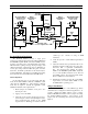
Typically, a Station GETC is installed in an EDACS
station cabinet just above each of the station's radio
assemblies as shown in Figure 2. The assembly is mounted
within a slide out shelf measuring 1.75 inches (one rack
unit) high by 19 inches wide.
Installation or removal of the shelf sub-assemblies
involves sliding the GETC shelf out of the cabinet and into
the service position. This position allows access to the
shelf's sub-assemblies. Install all components with the
appropriate screws, nuts, and washer hardware. Refer to
the MASTR IIe (LBI-38430) or MASTR III (LBI-38636)
Application Assembly Diagrams for detailed information
on installing the GETC Shelf.
Observe basic safety precautions to prevent injury or
equipment damage.
Upgrading Hardware
GETC Shelves 19D901868G3 which are upgrading to
the 349A9607G4 or G5 software must ensure their
hardware is upgraded to the proper level. (The
19D901868G4 GETC Shelf meets all Group 5
requirements.)
Upgrading the hardware involves three elements:
• The microprocessor U1, 19A705557P1 (80C32), is
replaced with a faster “Speedy” microprocessor
RYT 121 6060/A (80C320).
• Replacing the AMPS modem chips U4 and U19
with the TI AMPS modem chips 19A704727P4.
• Installing a Ferrite Toroid on the Turbo Board
harness to suppress EMI spurs at 74 MHz.
The replacement microprocessor and Ferrite Toroid are
available in the field installable upgrade kit SPK9505. If
replacement of the modem chips is necessary, they must be
ordered separately. Refer to LBI-38894 and LBI-38822 for
complete installation instructions.
GETC Logic Board Installation
This manual assumes the GETC Logic Board
(19D904266G1 or G4) is previously installed, setup for the
default configuration (Wideband EDACS Station), and
fully operational. If you suspect that the GETC Logic
board is not operating properly, refer to the
Troubleshooting section in this manual.
Turbo Board Installation
This manual assumes the Turbo Board is previously
installed and fully functional. If, after installing or
attempting to install the Turbo Software, the Turbo Board
is not functioning properly, refer to the Troubleshooting
section. Additional maintenance information is also
available in LBI-38822, SRN1060 and SRN1062.
CABINET
REPEATER
CHANNEL #5
REPEATER
SPACE
STATION GETC
POWER SUPPLYPOWER SUPPLY
STATION GETC
SPACE
REPEATER
CHANNEL #3
CHANNEL #4
REPEATER
STATION GETC
SPACE
POWER SUPPLY
REPEATER
CABINET
POWER SUPPLY
STATION GETC
SPACE
REPEATER
CHANNEL #1
CHANNEL #2
REPEATER
STATION GETC
SPACE
POWER SUPPLY
REPEATER
CABINET
DISTRIBUTION
PANEL
DISTRIBUTION
PANEL
DISTRIBUTION
PANEL
Figure 2 - Typical Five Channel Repeater
Cabinet