
Remote Starter User Manual


CONFIGURATION LBI-38988
Rev. B 15
Rockwell Modem Installation
The Rockwell Modem provides a high speed
synchronous serial interface between the Station GETC and
the CEC/IMC's Uplink GETC. The Station GETC uses the
modem to send and receive serial digital data representing
GID information, polling messages, keying messages, and
channel assignments. Data transfer rates are 9600 bits per
second (bps) using dedicated 3002 data grade four-wire
audio lines. Technical specifications for the modem may be
found in LBI-33031. Information on installing and testing
the modem may be found in LBI-38894, and LBI-38822.
Modem Alignment
Use the following steps to set up the basic audio line
levels. If the Station GETC is linked to a MultiSite system
other than the CEC/IMC (i.e. Data Gateway), different
levels may be required. Consult the applicable system
installation manual for the required levels.
1. Ensure jumpers are installed on J11 pins 1 & 2
and J12 pins 1 & 2.
2. Apply power to the GETC.
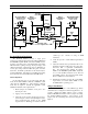
3. Adjust the receive level by monitoring U18 pin 1
(refer to Figures 3 and 4) and adjusting the receive
level potentiometer R1 (located on the GETC
Logic Board) for 400 mVpp as measured with an
oscilloscope (85 mVrms if using an RMS
Voltmeter).
4. Verify the presence of demodulated signal data at
TP107.
5. Adjust the transmit level potentiometer R2 for the
maximum output level allowed by the phone line,
microwave link, or equivalent communication
line. For telephone lines linking the Station
GETC to the CEC/IMC Uplink GETC, adjust R2
for .77 Vrms (0 dBm) measured across J6-8 and
J6-9 (TB10-1 and 2). For microwave links, adjust
R2 for -10 dBm across J6-8 and J6-9.
6. Initialize the modem by pressing S4 (on the GETC
Logic Board) to reset the Station GETC or cycle
the GETC Shelf's operating power.
Jumper Installation
There are a few jumpers on the GETC Logic Board
which must be re-configured for different applications. To
properly configure the GETC jumpers, refer to jumper
tables in SRN1060 and install or remove jumpers according
the intended GETC application. The location of the
jumpers may be found using the board layout diagram in
Figure 4.
68
1
2
52
12
5
T1
J6-07
Telephone Line
J6-06
J67
R36
604
D11 D10
R1
5K
2
3
1
U18A
4558
J11
Demodulated
Rx Data
TP107
Rockwell
Modem
19A705178
J3C-22
J3A-32
J3C-24
J3A-31
R2
1K
R38
220
7
6
U18B
4558
D13 D12
R146
604
68
52
T2
Unmodulated
Tx Data
TP105
J6-09 J6-08
Telephone Line
Level Adjustments
D0
4
D1
5
D2
6
D3
7
D4
8
D5
9
D6
10
D7
11
19 21
U19
Rx Tx
Serial Data
Parallel
Data Bus
Receiving Half of
Telephone Line
Transmitting Half of
Rx
Level
Tx
Level
Figure 3 - GETC Phone Line Level Adjustments