
Remote Starter User Manual


LBI-38988 CONFIGURATION
22 Rev. B
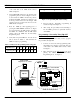
of the serial cable to the GETC Shelf connector
J100, see Figure 5.
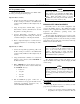
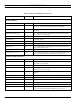
2. Set the GETC DIP switches S1, S2, and S3 for the
programming mode as shown in Figure 6. Set S2-
8, S3-3 and S3-6 to OPEN. All other S3 positions
should be CLOSED. Switches S1-1 thru S2-7 can
be in any position and need not be changed. DIP
switches S1-S3 are located near the front of the
GETC Shelf, see Figure 4.
3. Reset the GETC by either applying power or
pressing the GETC RESET switch S4, see Figure
4, located just below the DIP switches. Resetting
the GETC, in combination with the DIP switch
settings, places the GETC into the Personality
Programming mode.
4. Verify that front panel LEDs L3, L4, and L5 are
ON, as shown in Table 5. This indicates the
GETC is ready for programming.
Table 5 - Indicators in Programming Mode Using J100
LED Indicators L1 L2 L3 L4 L5 L6 L7
Programming Mode
❍❍●●●❍❍
Legend: ❍ = OFF ● = ON ❉ = FLASHING
5. Proceed with the Personality programming as
described in TQ-3357 Chapter 4.
6. After saving the personality and downloading it
into the GETC, perform an operational checkout
of the GETC.
Programming a Personality Using TQ-3357
Version 4.03 (or later)
When using TQ-3357 Version 4.03 (or later), program
the personality through J104.
1. Connect one end of the serial programming cable
(TQ-3360) to the computer. Connect the other end
of the cable to the GETC Shelf connector J104.
See Figure 7.
2. Move Switch S2 on the Turbo Board to the front
placing the GETC into the Personality
Programming mode. See Figure 7.
S4
S3S2S1
L1 L2 L3 L4 L5 L6 L7
T1 T2
U18R1
1
1
1
1
1
U19
U3
U2
U1
U4
J3
J49
J27
J10
J9 J8 J5
J19
J7
TP107
Software Disk
TQ-3357 V3 or earlier
To
COM 1 or
J100
J8
Harness 19C336863G2
TQ-3360
TQ3357
GETC Shelf 19D901868G3
Cable
1
U19
J3
J49
TP107
U1
U2
Turbo Board Lightning GETC
COM 2
Dip Switches S1-S3
Switch S4
Figure 5 - System Hook-Up Using J100
1234567
8
S1
12345678
S2
12345678
S3
OPEN
OPEN
OPEN
Figure 6 - Programming DIP Switch Settings