ADSL Modem HM210dp/di - User Guide ADSL Modem HM210dp/di User Guide © Ericsson AB 2003 All rights reserved
Copyright This manual is published by Ericsson AB, without any warranty. Improvements and changes to this manual necessitated by typographical errors, inaccuracies of current information, or improvements to programs and/or equipment, may be made by Ericsson AB at any time and without notice. Such changes will, however, be incorporated into new editions of this manual. All rights reserved.
Contents 1 2 3 Introduction 6 1.1 Features 6 1.2 1.3 Package Contents System Requirements 6 6 Hardware Description and Connection 8 2.1 2.2 2.3 Front Panel and LED Indicators Back Panel and Connectors Placement 8 9 9 2.4 Connecting the Hardware 11 3.1 Configuring your PCs as DHCP Clients 3.1.1 In Windows 95, 98 and Me 3.1.2 In Windows 2000 and XP Assigning Static IP Information to your PCs 11 11 11 12 Getting Started with the Configuration Manager 13 4.1 4.2 4.3 13 15 16 17 18 4.
7.1 7.2 7.3 8 9 10 11 4 (98) 34 34 34 36 36 36 37 37 37 38 38 NAT Configuration 39 8.1 8.2 8.3 8.4 8.5 39 39 41 42 43 44 45 46 47 49 50 Default NAT Setup Viewing NAT Configuration Viewing NAT Rules and Rule Statistics Viewing Current NAT Translations Adding NAT Rules 8.5.1 The NAPT Rule 8.5.2 The RDR Rule 8.5.3 The BASIC Rule 8.5.4 The FILTER Rule 8.5.5 The BIMAP Rule 8.5.6 The PASS Rule DNS Configuration 51 9.1 9.2 51 51 DNS Relay Overview Configuring DNS Relay RIP Configuration 54 10.
12.3 12.4 12.5 Image Upgrade Diagnostics Port Settings 72 74 75 12.6 View System Alarms 76 13 View DSL Parameters 77 14 Troubleshooting 80 14.1 14.2 14.3 81 81 81 15 LEDs Internet Access Configuration Manager Program Important Information 83 15.1 15.2 83 83 83 87 87 90 90 91 91 91 Product Care and Maintenance Regulatory Information 15.2.1 EU Directives 15.2.2 Safety Approvals 15.2.3 EMC Approvals 15.2.4 Telecom Approval 15.2.5 Caution 15.2.6 Power Supply 15.2.
Introduction 1 Introduction Congratulations on becoming the owner of an Ericsson ADSL Modem HM210dp/di. Your LAN (Local Area Network) will now be able to access the Internet using your high-speed ADSL connection. This User Guide describes how to install and set up your HM210dp/di in a Windows environment, and how to customize its configuration to get the most out of your new product. 1.1 Features The ADSL Modem HM210 comes in two versions: HM210dp and HM210di.
Introduction • One or more computers each containing an Ethernet 10Base-T/100Base-T network interface card (NIC). • An Ethernet hub/switch, if you are connecting the device to more than one computer. • For system configuration using the built-in Configuration Manager program: a web browser such as Internet Explorer v5.0 or later, or Netscape v5.0 or later.
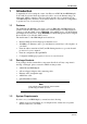
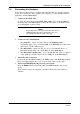
Hardware Description and Connection 2 Hardware Description and Connection 2.1 Front Panel and LED Indicators The front panel of the HM210dp/di contains five control lamps (LEDs) that indicate the status of the modem: Figure 1: Front Panel of HM210dp/di Label Color Function PWR green ON: Unit is powered on. OFF: Unit is powered off. DIAG green Flashes ON/OFF at boot-up to indicate that the device software is operational. LAN green OFF: No Ethernet link detected.
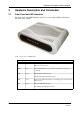
Hardware Description and Connection 2.2 Back Panel and Connectors The back panel of the HM210dp/di contains the connectors for the unit’s data and power connections as described below: Figure 2: Back Panel of HM210dp/di Label Function DSL Connects the HM210dp/di to an ADSL outlet (splitter/filter or phone outlet) using the supplied ADSL Line cable. LAN Connects the HM210dp/di to your PC's Ethernet port, or to the uplink port on your LAN's hub, using the supplied Ethernet cable.
Hardware Description and Connection 2.4 Connecting the Hardware Follow the procedures below to connect related devices. Before you begin, turn the power off for all devices. These include your computer(s), your LAN hub/switch (if applicable), and the HM210dp/di. 1 Connect to the ADSL Line. Connect one end of the provided ADSL Line cable to the port labeled DSL on the back panel of the HM210dp/di. Connect the other end to your ADSL service port (splitter/filter or phone outlet).
Local PC Configuration 3 Local PC Configuration By default, the HM210dp/di acts as DHCP server that automatically assigns all required Internet settings to your PCs, i.e., the DHCP clients. The predefined IP address and DHCP pool is as below: LAN Port IP address 192.168.1.1 Subnet Mask 255.255.255.0 DHCP pool 192.168.1.
Local PC Configuration 3.2 5 In the Internet protocol (TCP/IP) Properties dialog box, click the radio button labeled Obtain an IP address automatically. Also click the radio button labeled Obtain DNS server address automatically. 6 Click OK twice to confirm and save your changes, and then close the Control Panel.
Getting Started with the Configuration Manager 4 Getting Started with the Configuration Manager Your HM210dp/di includes a web-based Configuration Manager, which enables you to configure the device settings to meet the needs of your network. 4.1 Accessing the Configuration Manager You can access the Configuration Manager from any computer connected to the HM210dp/di.
Getting Started with the Configuration Manager After a successful login, the System View page appears. Figure 4: System View The System View table provides a snapshot of your system configuration. You can click on the provided links that enable you to configure each setting (if available). Refer to the appropriate chapters in this document for more information.
Getting Started with the Configuration Manager 4.2 Commonly Used Buttons and Icons Button / Symbol Function Stores in temporary system memory any changes you have made on the current page. Redisplays the current page with updated statistics. When accumulated statistics are displaying, this button resets the statistics to their initial values. Launches the online help for the current topic in a separate browser window. Help is available from any main topic page. Delete an entry. Modify an entry.
Getting Started with the Configuration Manager 4.3 Committing Changes to Permanent Storage Whenever you change system settings, the changes are initially placed in a temporary storage (called random access memory or RAM). Your changes are made effective when you submit them, but will be lost if the device is reset or turned off. Follow these steps to commit changes to permanent storage. 1 Select Admin > Commit & Reboot.
Getting Started with the Configuration Manager 4.3.1 Rebooting the HM210dp/di using the Configuration Manager If, after rebooting the device, you find that it does not operate properly with the new configuration, you can reboot using options that reactivate a previous configuration or the factory default configuration. Figure 6: Reboot Mode page You can select from the following options when rebooting: Setting Description Reboot Reboots the device to activate your new settings (if any).
Getting Started with the Configuration Manager 4.4 Quick Configuration The Quick Configuration page allows you to quickly configure your HM210dp/di for Internet connection. Your ISP should provide you with necessary information to complete the quick setup. To quickly configure the system, go to Home > Quick Configuration.
Getting Started with the Configuration Manager Field Description Operation Mode Select Enabled. If set to Disabled, the device cannot provide Internet connectivity for your network. Encapsulation Select the connection type your ISP uses to communicate with your HM210dp/di. VPI and VCI Enter the VPI/VCI values given by your ISP. Bridge This setting enables or disables bridging between the HM210dp/di and your ISP. Your ISP may also refer to this using "RFC 1483" or "Ethernet over ATM".
Basic Configuration 5 Basic Configuration This chapter provides basic configuration instructions to get your HM210dp/di run and have your network connected to the Internet. The instructions assume that the HM210dp/di is not predefined with any ATM VC, PPP and IPoA settings. For each connection method, example parameters are given for your better understanding. You should consult with your ISP to determine your connection mode and enter the actual values provided by your ISP.
Basic Configuration Field Description VC Interface Select a VC interface from the available interfaces, e.g. aal5-0 . VPI and VCI Enter the VPI/VCI values given by your ISP, e.g. 0/33 Mux Type Select LLC or VC as required by your ISP. Max Proto per AAL5 Keep the default 2. c d After entering the fields above, click the Submit button. When the confirmation page appears, click Close. You will return to the ATM VC Configuration table and see the newly added ATM VC entry.
Basic Configuration Figure 10: EOA Interface - Add b Enter the provided fields as below: Field Description EOA Interface Select an EoA interface from the available interfaces, e.g. eoa-0 . Interface Sec Type Public Lower Interface Select the ATM VC interface you created in Step 1, e.g. aal5-0 . Config. IP Address/Net Mask 0.0.0.0 / 0.0.0.0 To use the HM210dp/di as a bridge, you don't need to set the IP address and subnet mask. Just keep the default.
Basic Configuration Figure 11: RFC1483/Ethernet over ATM(EoA) Config 3 Enable Bridging function: a Select Bridging > Bridging page to display the Bridge Configuration page. b c Select eth-0 from the list and click Add. Select the EOA interface to be used (e.g. eoa-0 ) from the drop-down list, and then click Add. Set the Bridging item to Enable and click Submit. A confirmation page appears to confirm your changes. d 4 LAN configuration: a b Select Bridging > LAN Config.
Basic Configuration Figure 12: LAN Configuration 5 5.1.2 Commit your changes: Select Admin > Commit & Reboot and click Commit to store your changes to permanent memory. Check Your Connection Status Select Home > System Mode. The WAN Interface item should display the interface you created to communicate with your ISP. A green ball in the Status field indicates a successful connection. Figure 13: WAN IF Status 5.1.
Basic Configuration • Option 2: Your client use PPPoE software to connect to your ISP. Just keep your PC's setting as a DHCP client and execute the PPPoE software to make the connection. 5.2 PPP Connection Mode 5.2.1 Configuring the HM210dp/di 1 Creating an ATM VC interface: a Select Routing > ATM VC > Add. The ATM VC - Add page appears: Figure 14: ATM VC - Add b Enter the provided fields as below: Field Description VC Interface Select a VC interface from the available interfaces, e.g.
Basic Configuration Figure 15: ATM VC Configuration 2 Creating a PPP interface: a Select Routing > PPP > Add to add a new PPP interface: Figure 16: PPP Interface - Add b 26 (98) Enter the provided fields as below: EN/LZT 108 6492 R1 April 2003
Basic Configuration Field Description PPP Interface Select a PPP interface from the available interfaces, e.g. ppp-0 . ATM VC Select the ATM VC you created in step 1, e.g. aal5-0 . IPF Type Public Status Select Start or StartOnData Start - To establish connection whenever you turn on the HM210dp/di. StartOnData - To establish a connection whenever the device gets a request to connect to the Internet, such as when you open a browser requesting for web pages.
Basic Configuration Figure 17: PPP Configuration 5.2.2 Check Your Connection Status Select Home > System Mode. The WAN Interface item should display the interface you created to communicate with your ISP. A green ball in the Status field indicates a successful connection. Figure 18: WAN IF Status 5.2.3 Configuring the PC Keep your PC's setting as a DHCP client. No further configuration is required. 5.3 Router Connection Mode This section describes both RFC1577 and RFC1483 Router connection methods.
Basic Configuration Figure 19: ATM VC - Add b Enter the provided fields as below: Field Description VC Interface Select a VC interfacce from the available interfaces, e.g. aal5-0 . VPI/VCI Enter the VPI/VCI values given by your ISP, e.g. 0/34 Mux Type Select LLC or VC as required by your ISP. Max Proto per AAL5 Keep the default 2. c d After entering the fields above, click Submit. When the confirmation page appears, click Close.
Basic Configuration Figure 21: IPoA Interface - Add b Enter the provided fields as below: Field Description IPoA Interface Select an IPoA interface from the available interfaces, e.g. ipoa-0 . Conf. IP address Enter the IP address given by your ISP, e.g. 10.100.17.89 Interface Sec Type Select Public, Private or DMZ Netmask Enter the IP address given by your ISP, e.g. 255.255.255.248. RFC 1577 For RFC 1577-Classical IP and ARP over ATM, select Yes For RFC 1483 Router, select No.
Basic Configuration Figure 22: IPoA Configuration 3 Mapping IPoA interface to a lower interface: In the IPoA Configuration table, locate the new IPoA entry and click Map in the "Action" column. Figure 23: IPoA Interface - Map On IPoA Interface - Map page, from the drop-down list select the ATM VC you created in step 1 to be mapped to this IPoA interface and then click Add. Click Close to exit the confirmation page. 5.3.2 Check Your Connection Status Select Home > System Mode.
Configuring IP Routes 6 Configuring IP Routes You can use the Configuration Manager to define specific routes for your Internet and network data. This chapter provides instructions for creating routes. Most users do not need to define IP routes. You may need to define routes if: • • • 6.1 Your network setup includes two or more networks or subnets You connect to two or more ISP services You connect to a remote corporate LAN.
Configuring IP Routes 6.2 Adding IP Routes 1 Select Routing > IP Route > Add. The IP Route - Add page appears: Figure 26: IP Route - Add 2 Specify the destination, network mask, and gateway or next hop for this route. To create a route that defines the default gateway for your LAN, enter 0.0.0.0 in both the Destination and Netmask fields. Enter your ISP's IP address in the Gateway/NextHop field. Note: You cannot specify the interface name, route type or route origin.
DHCP Configuration 7 DHCP Configuration You can configure your network and HM210dp/di to use the Dynamic Host Configuration Protocol (DHCP). This chapter provides instructions for implementing DHCP on your network. 7.1 HM210dp/di DHCP Modes The HM210dp/di can be configured as a DHCP server, DHCP relay agent, or, in some cases, a DHCP client. • DHCP server - It will maintain the pool of addresses and distribute them to your LAN computers.
DHCP Configuration Figure 28: DHCP Server Pool - Add The Start IP Address, End IP Address, Net Mask and Gateway Address fields are required, the others are optional. Field Description Start/End IP Addresses Specify the lowest and highest IP addresses in the pool. Mac Address Allows you to assign a specific IP address to a specific computer, identified by this MAC address. If this is the case, you must have specified the same IP address in both the Start/End IP Address fields.
DHCP Configuration 7.2.2 Field Description SDSN ... SWINS (optional) The IP addresses of devices that perform various services for DHCP clients. 3 Click the Submit button. A configuration page appears to indicate that the pool has been added successfully. 4 Click Close to return to the DHCP Configuration page. Enabling DHCP Server Mode 1 Select LAN > DHCP Mode, and from the "DHCP Mode" drop-down list select DHCP Server. Click the Submit button. A page appears to confirm the change.
DHCP Configuration • Exclude IP addresses within its range from distribution. To exclude an IP address, enter it in the field provided and click Add. If you want to change other attributes, you must delete the pool and create a new one. After entering your changes, click theSubmit button. Select Admin > Commit & Reboot and click Commit to save your changes to permanent storage. 7.2.
DHCP Configuration 7.3.2 7.3.3 38 (98) Enabling DHCP Relay Mode 1 Select LAN > DHCP Mode and from the "DHCP Mode" drop-down list select DHCP Relay. Click the Submit button. A page appears to confirm the change. 2 Select Admin > Commit & Reboot and click Commit to save your changes to permanent storage.
NAT Configuration 8 NAT Configuration This chapter provides an overivew of Network Address Translation (NAT) and instructions for modifying the default configuration on your HM210dp/di. 8.1 Default NAT Setup By default, NAT is enabled, with an Network Address Port Translation (NAPT) rule configured that translates any private address on the LAN side to your ISP-assigned public IP address on the WAN side. 8.2 Viewing NAT Configuration To view your NAT settings, select Services > NAT.
NAT Configuration Field Description TCP Close Wait (sec) When in the TCP session's closing state, the session will timeout if no packets are received for the specified time. TCP Def Timeout (sec) When in the TCP session's establishing state, the session will timeout if no packets are received for the specified time. UDP Timeout (sec) Same as TCP Idle Timeout, but for UDP packets. ICMP Timeout (sec) Same as TCP Idle Timeout, but for ICMP packets.
NAT Configuration Figure 32: NAT Rule Global Statistics page 8.3 Viewing NAT Rules and Rule Statistics To view the NAT Rules currently defined on your system, select Services > NAT > NAT Rule Entry.
NAT Configuration Figure 33: NAT Rule Configuration page To view data on how often a specific NAT rule has been used, click Stats in the Action column. A page similar to the one below appears: Figure 34: NAT Rule Statistics page The statistics show how many times this rule has been invoked and how many curently active sessions are using this rule. 8.
NAT Configuration Figure 35: NAT Translations For each current NAT translation session, the table contains the following fields: 8.5 Field Description Trans Index The sequential number assigned to the IP session used by this NAT translation session. Rule ID The ID of the NAT rule invoked. Interface The device interface on which the NAT rule was invoked (from the rule definition). Protocol The IP protocol used by the data packets that are undergoing translations (from the rule definition).
NAT Configuration 8.5.1 The NAPT Rule The NAT flavor NAPT was used in your default configuration. The NAPT flavor translates all LAN-side private source IP addresses to a single public IP address. It also translates the source port numbers to port numbers that are defined on the NAT Global Configuration page. 1 Select Services > NAT > NAT Rule Entry > Add. Figure 36: Nat Rule NAPT - Add 2 3 4 5 6 7 When you have completed entering all information, click the Submit button.
NAT Configuration 10 On the NAT Configuration page, click the Submit button. A page appears to confirm your changes. 11 Select Admin > Commit & Reboot and click Commit to save your changes to permanent storage. 8.5.2 The RDR Rule You can create an RDR rule to make a computer on your LAN, such as a Web or FTP server, available to Internet users without requiring you to obtain a public IP address for that computer.
NAT Configuration 4 5 6 7 8 In the Local Address From/To fields, type the same private IP address, or the lowest and highest IP addresses in a range: If you type the same IP address in both fields, incoming traffic that matches the criteria of this rule will be redirected to that IP address. If you type a range of IP addresses, incoming traffic will be redirected to any available computer in that range.
NAT Configuration Figure 38: NAT Rule BASIC - Add 1 2 3 4 5 When you have completed entering all information, click the Submit button. A page appears to confirm the change. 6 Click Close to return to the NAT Configuration page. The new rule should now be displayed in the NAT Rule table. On the NAT Configuration page, ensure that the Enable radio button is selected. 7 8.5.4 Display the NAT Rule - Add page, select BASIC as the Rule Flavor and type a Rule ID.
NAT Configuration You can use the FILTER rule if you want an address translation to occur only when your LAN computers initiate access to specific destinations. The destinations can be identified by their IP addresses, server type (such as FTP or Web server), or both. Figure 39: NAT Rule FILTER - Add 1 2 3 4 5 48 (98) Display the NAT Rule - Add page, select FILTER as the Rule Flavor and type a Rule ID. Select the interface and, if desired, a protocol that this rule applies to.
NAT Configuration 8 On the NAT Configuration page, ensure that the Enable radio button is selected. 9 On the NAT Configuration page, click the Submit button. A page appears to confirm your changes. 10 Select Admin > Commit & Reboot and click Commit to save your changes to permanent storage. 8.5.5 The BIMAP Rule Unlike the other NAT flavors, the BIMAP flavor performs address translations in both the outgoing and incoming directions.
NAT Configuration 8.5.6 8 On the NAT Configuration page, click the Submit button. A page appears to confirm your changes. 9 Select Admin > Commit & Reboot and click Commit to save your changes to permanent storage. The PASS Rule You can create a PASS rule to allow a range of IP addresses to remain untranslated when another rule would otherwise do so. Figure 41: NAT Rule PASS - Add The PASS rule must be assigned a rule ID that is a lower number than the ID assigned to the rule it is intended to pass.
DNS Configuration 9 DNS Configuration This chapter describes how to configure the DNS Relay function on the HM210dp/di. 9.1 DNS Relay Overview When performing DNS relay, the HM210dp/di itself is not a DNS server, it forwards DNS requests from LAN PCs to a DNS server at the ISP. It then relays the DNS response to the PCs. The HM210dp/di learns DNS addresses in either or both of the following ways: • • 9.2 Learned through PPP Configured on the HM210dp/di.
DNS Configuration Figure 43: PPP Interface - Detail 52 (98) • Option 2: Configuring DNS on the HM210dp/di: You can configure the DNS server address to be relayed on the router if one of the following circumstances applies: - Not using PPP connection to the ISP (or a protocol other than PPP is used, such as EoA). - You use PPP connection and Use DNS is already enabled. Then these configured addresses will be used in addition to those DNS addresses learned through PPP.
DNS Configuration Figure 44: DNS Configuration b c Type the IP address of the DNS server in an empty row and click Add. Click the Enable radio button, and then click Submit. Select Admin > Commit & Reboot and click Commit to save your changes to permanent storage.
RIP Configuration 10 RIP Configuration The HM210dp/di can be configured to communicate with other routing devices to determine the best path for sending data to its intended destination. This chapter describes how to configure your HM210dp/di to use one of these, called the Routing Information Protocol (RIP). Most small home or office networks do not need to use RIP. You may want to configure RIP if any of the following circumstances apply to your network: 10.
RIP Configuration For communication with RIP-enabled devices on your LAN, select eth-0 or the name of the appropriate virtual Ethernet interface. For communication with your ISP or a remote LAN, select the corresponding ppp, eoa, or other WAN interface. 4 5 6 7 Select a Metric value (hop count) for the interface. You can select any integer from 1 to 15. Select a Send and Receive Mode.
RIP Configuration 10.
Firewall Configuration 11 Firewall Configuration The Configuration Manager provides built-in firewall functions, enabling you to protect the system against denial of service (DoS) attacks and other types of malicious accesses to your LAN. You can also specify how to monitor attempted attacks, and who should be automatically notified. 11.
Firewall Configuration Field Description Attack Protection Select Enable to use the built-in firewall protections that prevent the following common types of attacks: IP Spoofing: Sending packets over the WAN interface using an internal LAN IP address as the source address. Tear Drop: Sending packets that contain overlapping fragments. Smurf and Fraggle: Sending packets that use the WAN or LAN IP broadcast address as the source address.
Firewall Configuration Field Description E-mail ID of Admin 1/2/3 Specifies the e-mail address(es) of the administrator(s) who should receive notices of any attempted firewall violations. Type the address(es) in standard internet e-mail address format, e.g. jxsmith@onecompany.
Firewall Configuration 11.2 IP Filter Configuration The IP filter feature enables you to create rules that control the forwarding of incoming and outgoing data between your LAN and the Internet. 11.2.1 Viewing Your IP Filter Configuration Select Services > IP Filter. The IP Filter page appears: Figure 48: IP Filter Configuration page 11.2.
Firewall Configuration 11.2.3 • Security Level: When High is selected, only those rules that are assigned a security value of High will be in effect. The same is true for the Medium and Low settings. When None is selected, IP Filtering is disabled. • Private/Public/DMZ Default Action: This setting specifies a default action to be taken (Accept or Deny) on private, public, or DMZ-type device interfaces when they receive packets that do not match any of the filtering rules.
Firewall Configuration Figure 49: IP Filter Rule - Add 2 62 (98) Enter or select data for each field that applies to your rule: EN/LZT 108 6492 R1 April 2003
Firewall Configuration Field Description Rule ID Rules are processed from lowest to highest on each data packet, until a match is found. It is recommended that you assign rule IDs in multiples of 5 or 10 (e.g. 10, 20, 30) so that you leave enough space between them for inserting a new rule if necessary. Action The action can be Accept (forward to destination) or Deny (discard the packet). Direction Incoming refers to packets coming from the LAN, and outgoing refers to packets going to the Internet.
Firewall Configuration Field Description Src IP Address IP address critera for the source computer(s) from which the packet originates. Use the following expressions to specify IP: any: any source IP address lt: less than lteq: less than or equal to gt: greater than eq: equal to neq: not equal to range: within the specified range, inclusive out of range: outside the specified range self: the IP address of the router interface on which this rule takes effect.
Firewall Configuration Field Description TCP Flag Specifies whether the rule should apply only to TCP packets that contain the synchronous (SYN) flag, only to those that contain the non-synchronous (NOT-SYN) flag, or to all TCP packets. This field will be dimmed (unavailable for entry) unless you selected TCP as the protocol. ICMP Type Specifies whether the value in the type field in ICMP packet headers will be used as a criteria. The code value can be any decimal value from 0 to 255.
Firewall Configuration Field Description TOD Rule Status The Time of Day Rule Status determines how the Start Time/End Time settings are used. Enable: (Default) The rule is in effect for the specified time period. Disable: The rule is not in effect for the specified time period, but is effective at all other times. 3 4 5 When you are done selecting criteria, ensure that the Enable radio button is selected and then click the Submit button.
Firewall Configuration 11.2.4 Viewing IP Filter Statistics To view statistics on how many packets were accepted or denied for a rule, select Services > IP Filter > Stats in the row corresponding to the rule: Figure 50: IP Filter Rule - Statistics 11.2.
Firewall Configuration 11.3 Field Description IP Address The IP addresses involved in the communication. The first one shown is the initiator of the communication. Port The hardware addresses of the ports involved in the commmunication. In/Out Rule Index The number of the IP Filter rule that is applied to this session (assigned when the rule was created). In/Out Action The action (accept, deny, or unknown) being taken on data coming in to or going out from the interface.
Firewall Configuration Figure 52: Blocked Protocols Check the protocol type you want to block and click the Submit button. Make sure to use the Commit feature to save your changes to the permanent memory. To unblock a specific protocol, uncheck the protocol and repeat the submit and commit tasks.
Administration Tasks 12 Administration Tasks 12.1 Changing the System Date and Time The HM210dp/di keeps a record of the current date and time, which it uses to calculate and report various performance data. You can select Home > Modify to change the date and time as required. You may also specify the host name and the domain name in the fields provided.
Administration Tasks 12.2 Adding Login User ID and Changing Login Password The first time you log into the Configuration Manager, you use the default User ID and Password (root and root). The system allows two levels of privilege: Root and User. Root privilege allows you to change and commit the device's settings while user privilege is provided with read-only access rights. To add login User ID or change login password: 1 Select Admin > User Config.
Administration Tasks Figure 56: User Config - Add 4 5 12.3 After making changes, click the Submit button. Select Admin > Commit & Reboot and click Commit to save your changes to permanent storage. Image Upgrade This option allows you to upgrade the HM210dp/di to new firmware. After upgrading, your customized configuration will still exist and not be reset to the factory defaults.
Administration Tasks 2 Click Upload to start the upgrade. After a few seconds, a message like the following should appear (the file name may differ): File: TEDsl.gsz successfully saved to the flash. Please reboot for the new image to take effect. 3 Power off the unit, wait a few seconds, and then turn it on again to activate the new software. Note: Do not interrupt the upgrade process. Otherwise it might cause damage to your router.
Administration Tasks 12.4 Diagnostics To perform diagnostics on ATM VC, select Admin > Diagnostics. Select the VC on which you want to execute diagnostics and then click Submit. The diagnostic result will be displayed. Note that only the VCs defined in the system will appear in the drop-down list.
Administration Tasks 12.5 Port Settings The router's HTTP/Telnet/FTP service are accessible using the standard port number 80, 23 and 21 respectively. It is possible that you want to designate a publicly accessible HTTP, Telnet or FTP server on your LAN side and you want to shift the router's HTTP/Telnet/FTP service to use a non-standard port number.
Administration Tasks 12.6 View System Alarms To display the alarm page select Admin > Alarm: Figure 60: Alarm page Each row in the table displays the time and date when an alarm occurred, the type of alarm, and a brief statement indicating its cause. You can click on the Refresh Rate drop-down list to select a recurring time interval after which the page will be redisplayed with new data.
View DSL Parameters 13 View DSL Parameters To view configuration parameters and performance statistics for the ADSL line, select WAN > DSL. The DSL Status page displays: Figure 61: DSL Status page The DSL Status page displays the current information on the DSL line performance. The page refreshes about every 10 seconds.
View DSL Parameters Figure 62: DSL Parameter From the DSL Status page you can click Stats to display DSL line performance statistics: 78 (98) EN/LZT 108 6492 R1 April 2003
View DSL Parameters Figure 63: DSL Statistics The DSL Statistics page reports error data relating to the last 15 mintues interval, the current day, and the previous day. At the bottom of the page, the Detailed Interval Statistics table displays links you can click to display detailed data for each 15 minute interval in the past 24 hours. For example, when you click on 1-4, data displays for the 15-minute such intervals that make up the prevous 4 hours (there are 16 of these) shows one such page.
Troubleshooting 14 Troubleshooting This chapter suggests solutions for problems you may encounter when installing or using your HM210dp/di, and provides instructions for using several IP utilities to diagnose problems.
Troubleshooting 14.1 LEDs Problem Troubleshooting Suggestion The PWR LED does not illuminate after product is turned on. Verify that you are using the power cable provided with the device and that it is securely connted to the HM210dp/di and a wall socket/power strip. The DSL LED does not illuminate after Verify that a standard telephone cable is securely connected phone cable is attached. to the DSL port and your wall phone jack.
Troubleshooting Problem Troubleshooting Suggestion You forgot/lost your Configuration Manager user ID and/or Password. You can reset the HM210dp/di to the default configuration by pressing the Reset button for 3 times on the back panel of the device (using a pointed object such as a paper clip). WARNING! Resetting the HM210dp/di removes any custom settings and returns all settings to their default values.
Important Information 15 Important Information 15.1 Product Care and Maintenance Note: These are important guidelines for safe and efficient use of your device. Read this information before using your Ericsson ADSL Modem HM210dp/di. Your ADSL Modem HM210dp/di is a highly sophisticated electronic device. To get the most out of your product, be sure to read the following text about product care, safety and efficient use. Do not expose the product to liquid or moisture.
Important Information 15.2.1.1 CE Requirement Hereby, Ericsson AB, declares that this ADSL Modem HM210dp/di is in conformity with the essential requirements and other relevant provisions of the R&TTE directive 1999/5/EC.
Important Information 15.2.1.
Important Information 86 (98) EN/LZT 108 6492 R1 April 2003
Important Information 15.2.2 Safety Approvals The HM210dp/di is approved according to the following safety standards: • • • UL 1950, 3rd Ed. CSA C22.2 No. 60950 IEC 60950 3rd Ed, 1999 15.2.2.
Important Information interference will occur in a particular installation. If this equipment does cause harmful interference to radio or television, which can be determined by turning the equipment off and on, the user is encouraged to eliminate the interference by one or more of the following measures: 88 (98) • • Reorient or relocate the receiving antenna of the affected equipment. Increase the separation between the ADSL Modem HM210dp/di and the affected equipment.
Important Information EN/LZT 108 6492 R1 April 2003 89 (98)
Important Information 15.2.4 Telecom Approval The HM210dp/di is approved according to the following telecom standard: • FCC Part 68 15.2.4.1 FCC Part 68 The Federal Communications Commission (FCC) has established Rules which permit this device to be directly connected to the telephone network. Standardized jacks are used for these connections. This equipment should not be used on party lines or coin phones.
Important Information 15.2.6 Power Supply The ADSL Modem HM210dp/di is equipped with one of the following external power supply adapters: For EU; OEM AA-161ABN, Input 230VAC/50Hz, Output - 16VAC/1A or OEM AA-1860BN; Input 230VAC/50Hz, Output - 18VAC/600mA. For US; OEM AA-161A; Input - 120VAC/60Hz, Output - 16VAC/1A or OEM AA-1860; Input - 120VAC/60Hz, Output - 16VAC/600mA. Note: The HM210dp/di is for use only with one of the above approved supplied power adapters.
Glossary Glossary ADSL Short for Asymmetric Digital Subscriber Line, a technology that allows more data to be sent over existing copper telephone lines (POTS). ADSL supports data rates of from 1.5 to 9 Mbps when receiving data (known as the downstream rate) and from 16 to 640 Kbps when sending data (known as the upstream rate). ARP Short for Address Resolution Protocol, a TCP/IP protocol used to convert an IP address into a physical address, such as an Ethernet address.
Glossary DMZ A Demilitarized Zone is used by a company that want to host its own Internet services without sacrificing unauthorized access to its private network. The DMZ sits between the Internet and an internal network's line of defense, usually some combination of firewalls and bastion hosts. DNS Short for Domain Name System (or Service), an Internet service that translates domain names into IP addresses. Because domain names are alphabetic, they're easier to remember.
Glossary accessing private networks connected to the Internet, especially intranets. All messages entering or leaving the intranet pass through the firewall, which examines each message and blocks those that do not meet the specified security criteria. There are several types of firewall techniques: • Packet filter: Looks at each packet entering or leaving the network and accepts or rejects it based on user-defined rules.
Glossary IGMP Short for Internet Group Management Protocol, the standard for IP multicasting in the Internet. It's used to establish host memberships in particular multicast groups on a single network. The mechanisms of the protocol allow a host to inform its local router, using Host Membership Reports, that it wants to receive messages addressed to a specific multicast group. IP address An identifier for a computer or device on a TCP/IP network.
Glossary Packet switching refers to protocols in which messages are divided into packets before they are sent. Each packet is then transmitted individually and can even follow different routes to its destination. Once all the packets forming a message arrive at the destination, they are recompiled into the original message.
Glossary PVC Short for Permanent Virtual Circuit, which is a logical point-to-point circuit between customer sites. PVCs are low-delay circuits because routing decisions do not need to be made along the way. Permanent means that the circuit is preprogrammed by the carrier as a path through the network. It does not need to be set up or disconnected for each session. RFC Short for Request for Comments, a series of notes about the Internet, started in 1969 (when the Internet was the ARPANET).
Glossary UDP Short for User Datagram Protocol, a connectionless protocol that, like TCP, runs on top of IP networks. Unlike TCP/IP, UDP/IP provides very few error recovery services, offering instead a direct way to send and receive datagrams over an IP network. It's used primarily for broadcasting messages over a network. Upstream The direction of an upstream signal is from the user's computer to the ISP/service provider (uploading).