
User guide

Hardware Description and Connection
EN/LZT 108 6492 R1 9 (98)
April 2003
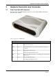
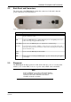
2.2 Back Panel and Connectors
The back panel of the HM210dp/di contains the connectors for the unit’s data and
power connections as described below:
Figure 2: Back Panel of HM210dp/di
Label Function
DSL
Connects the HM210dp/di to an ADSL outlet (splitter/filter or phone outlet) using the
supplied ADSL Line cable.
LAN
Connects the HM210dp/di to your PC's Ethernet port, or to the uplink port on your
LAN's hub, using the supplied Ethernet cable.
Reset button
(tiny hole)
Used to restore the HM210dp/di to its original factory default settings.
To reset the device to factory defaults, you don't need to power off the device. Just
push a paper clip into the hole and hold for 3 times before releasing. Then wait for the
device to finish boot-up.
Power
button
Used to switch the HM210dp/di ON and OFF.
PWR
Power socket for connecting the HM210dp/di to a power outlet by using the supplied
power adapter.
2.3 Placement
The HM210dp/di should be placed on a flat surface. Be sure to choose a location that
enables you to see the LEDs, is close to a power outlet, ADSL outlet, and the PC.
Note:
Proper ventilation is necessary to prevent the product
from over-heating. Do not block or cover the slots and
openings on the device, which are intended for
ventilation and proper operation.