LBI-38732D Operator’s Manual ® EDACS M-RK-II PORTABLE RADIO ericssonz
NOTICE! This manual covers Ericsson and General Electric products manufactured and sold by Ericsson Inc. NOTE! Repairs to this equipment should be made only by an authorized service technician or facility designated by the supplier. Any repairs, alterations or substitution of recommended parts made by the user to this equipment not approved by the manufacturer could void the user’s authority to operate the equipment in addition to the manufacturer’s warranty.
TABLE OF CONTENTS SAFETY INFORMATION . . . . . . . . . . . . . BATTERY CHARGING AND CARE . . . . . . . FOR BEST PERFORMANCE . . . . . . . . EXTENDED OPERATIONS . . . . . . . . . . . FCC LICENSING . . . . . . . . . . . . . . . . . TRANSCEIVER SERVICE . . . . . . . . . . . . INTRODUCTION . . . . . . . . . . . . . . . . . USER INTERFACE . . . . . . . . . . . . . . . . BUTTONS AND KNOBS . . . . . . . . . . . KEYPAD . . . . . . . . . . . . . . . . . . . DISPLAY . . . . . . . . . . . . . . . . . . . Messages . .
Clear Modes . . . . . . . . . . . . . . . . . Aegis Digital Mode . . . . . . . . . . . . . DTMF . . . . . . . . . . . . . . . . . . . . Error Messages . . . . . . . . . . . . . . . AEGIS PRIVATE AND VOICE GUARD PRIVATE MODES . . . . . . . . . . . . . . . . Transferring Keys Into The Radio . . . . . . Displaying The Currently Used Cryptographic Key Number . . . . . . . . . . . . . . . . . Key Zero . . . . . . . . . . . . . . . . . . . PRIVATE OPERATION . . . . . . . . . . . . . .
Sending An Individual Call (Trunked Mode Only) . . . . . . . . . . . TELEPHONE INTERCONNECT CALLS . . Receiving A Telephone Interconnect Call (Trunked Mode Only) . . . . . . . . . . . Sending A Telephone Interconnect Call (Trunked Mode Only) . . . . . . . . . . . DTMF Overdial/Conventional Mode Telephone Interconnect . . . . . . . . . PORTABLE DATA . . . . . . . . . . . . . . Data Displays . . . . . . . . . . . . . . Data Off Operation . . . . . . . . . . . . Data On Operation . . . . . . . . . . . .
SCANNING CONVENTIONAL CHANNELS . . ADDING CHANNELS TO A SCAN LIST . . . . DELETING CHANNELS FROM A SCAN LIST NUISANCE DELETE . . . . . . . . . . . . . . TURNING SCAN ON . . . . . . . . . . . . . . TURNING SCAN OFF . . . . . . . . . . . . . TYPE 99 DECODE (CONVENTIONAL ONLY) . OPERATING RULES AND REGULATIONS . . OPERATING TIPS . . . . . . . . . . . . . . . . INTRINSICALLY SAFE USAGE . . . . . . . . . BATTERY PACKS . . . . . . . . . . . . . . . . ACCESSORIES . . . . . . . . . . . . . . . . . GLOSSARY . . . .
SAFETY INFORMATION The Federal Communications Commission (FCC), with its action in General Docket 79-144, March 13, 1985, has adopted a safety standard for the human exposure to radio frequency (RF) electromagnetic energy emitted by FCC regulated equipment. Proper operation of this radio will result in user exposure far below the Occupational Safety and Health Act and Federal Communication Commission limits.
BATTERY CHARGING AND CARE Do not dispose of the battery pack in fire - it may explode, causing injury or death. Do not replace the battery in hazardous atmosphere locations. Do not carry battery loose in your pocket or purse. Do not attempt to repair battery. The product you have purchased contains a rechargeable battery. The battery is recyclable. At the end of its useful life under various state and local laws it may be illegal to dispose of this battery into the municipal waste stream.
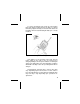
To remove the battery pack, push up on the battery latch and slide the battery pack to the right. To replace the battery, align the battery on the track and slide to the left until a click is heard, indicating the battery is correctly installed. Figure 1 - Installing And Removing The Battery Pack If the battery is to be charged on the radio, turn the power switch on the radio to the off position before charging.
FOR BEST PERFORMANCE 1. Charge battery to full capacity, 14 hours at the standard C/10 rate (capacity X .10). For "rapid" chargers, allow additional time (2-3 hours) for "topping off" the charge after it switches from "fast" to "slow". 2. Use the battery soon and use as much of the battery capacity as possible or practical. A battery that is charged and discharged completely will maintain the longest running time capacity.
EXTENDED OPERATIONS When operating in "Fringe Areas" at some distance from the System, the other party may not receive your transmission clearly. Also, you may notice that the background noise will increase on received signals. Moving to higher ground or moving closer to the System will help alleviate these problems. If moving closer to the System is not practical, communication may be improved by moving away from shielding structures.
FCC LICENSING This unit may or may not require a specific FCC license to operate. The FCC requires all transmitters in the conventional and some Trunked Systems to be licensed by the Federal Communications Commission. Some Trunked operations are now exempt from individual licensing requirements but must be operated in a licensed System. Consult your dealer regarding specific licensing information, or contact the Federal Communications Commission.
INTRODUCTION This manual describes how to use the EDACS M-RK II Portable Radio. The M-RK II is a synthesized, microprocessor-based, high performance portable FM radio providing reliable two-way communications in both the Enhanced Digital Access Communications System (EDACS) trunking environment and conventional communication systems. In the EDACS or trunked system mode, the user selects a communications system and group.
USER INTERFACE The M-RK II operating controls are located on the radio’s front, top and left panels. A 15-button keypad, liquid crystal display (LCD) for radio status information, microphone and speaker are on the front panel. The top panel houses a rotary SYSTEM/GROUP/CHANNEL knob, POWER ON-OFF/VOLUME control knob and a protected red EMERGENCY button. An OPTION button, CLEAR/MONITOR button and the Push-To-Talk (PTT) button are all located on the left side panel.
Figure 2 - M-RK II Portable Radio 15
Figure 3 - Top And Partial Left Panel Views 16
BUTTONS AND KNOBS This section describes the primary function of the button and knob controls. Other functions associated with these controls are detailed in later sections. SYSTEM /GROUP /CHANNEL KNOB Selects systems or groups/channels (depending on programming). This is a 16 - position rotary knob. See SYSTEM/GROUP/CHANNEL SELECTION for details. POWER ON-OFF /VOLUME KNOB Applies power to the radio and adjusts the receiver’s volume.
EMERGENCY/HOMEBUTTON The EMERGENCY/HOME button is used to automatically select a desired Group and/or System by pressing and holding the button for a preprogrammed duration. The EMERGENCY/HOME button is also used to declare emergencies by pressing and holding the button for a pre-programmed duration. Emergency messages may only be issued on EDACS systems. OPTION BUTTON (1) Programmable per system. (2) Performs the backspace function during data entry.
programmed for the selected channel. PUSH-TOTALK BUTTON (PTT) Enables the radio’s transmitter. Releasing PTT returns the radio to the receive mode. KEYPAD The keypad layout is similar to a standard telephone keypad but with three additional buttons at the top for a total of 15 keys. In addition to numbers, most of the keys have special functions and are labeled as such using a symbol or abbreviated word describing its primary function. Numeric entry is a secondary function of the keys.
m ., within a list. Press to scroll in increasing order, to scroll in decreasing order. To auto-ramp press and hold either key. Primary function - accesses the menu list. This is a list of additional features that are not available directly from the keypad. See MENU for details. Secondary function - activates a selected item within a list. After the menus list is accessed, select a menu item from the list via or and activate it with this key.
3 69 7 8 * # order, or to select a set (bank) of groups for SYSTEM/GROUP/ CHANNEL knob selection (depending on programming). See SYSTEM/ GROUP/CHANNEL SELECTION for details. Toggles scan operation on and off. When the radio is scanning, SCN is on and all groups or channels in the scan list of the currently selected system are scanned. Adds or deletes selected groups or channels from the scan list of the currently selected system. See the trunked and conventional scan sections for details.
0 special call function. See Individual Calls for details. Inverts the display’s two alphanumeric character lines for viewing from above; useful when the radio is attached to the user’s belt. DISPLAY The radio’s display is shown below. The two character lines are used to display system, group and channel names and also operational messages to the user. Each line contains eight alphanumeric character blocks. The 15 status indicators are used to show the various operating conditions of the radio.
Messages During radio operation, various messages are displayed on either line one or line two. Typical messages include control channel status information, such as system busy or call denied, or messages associated with the radio’s operation, (i.e. volume or contrast adjust). These messages are described below. Message Name QUEUED Call Queued - Trunked mode only. Indicates the system has placed the call in a request queue. SYS BUSY System Busy - Trunked mode only.
CC SCAN Control Channel Scan - Trunked mode only. Indicates the control channel is lost and the radio has entered the Control Channel Scan mode to search for the control channel. WA SCAN Wide Area Scan - Trunked mode only. Indicates the control channel is lost and radio has entered the Wide Area Scan mode to search for a new system (if enabled through programming). TALKARND Talk-around - Conventional mode only. Indicates the radio is operating on conventional channels in talkaround mode (no repeater).
is being received. This message will be flashing on line two. *TXEMER* Transmit Emergency - Trunked mode only. Indicates an emergency call has been transmitted. This message will be flashing on line two. VOL = 31 Volume Level - Indicates the current volume level. The volume level display ranges from OFF (silent) to 31 (loudest). LOW BATT Battery Low - Indicates the battery level is too low for transmission.
individual call is being received by an unknown radio ID. This bypasses when the call is updated. TX DATA Transmit Data - Trunked mode only. Indicates when a data call is being transmitted. Displayed on line one. RX DATA Receive Data - Trunked mode only. Indicates when a data call is being received. Displayed on line one. DATA OFF Data Off - Trunked mode only. Indicates when radio is in data disable state. Displayed on line one. Data On - Trunked mode only.
one for two seconds. KEY ZERO Key Zero PVT DIS Private Disabled - Indicates that cryptographic keys have been erased from radio memory. - Indicates that the group or channel is not programmed for private mode operation. FRCD PVT Forced Private - Indicates that group or channel is pre-programmed for private mode operation and clear mode is not possible. NO KEY # No Key Number - Indicates that the correct cryptographic key is not loaded for the selected group or channel.
Status Indicators The 15 status indicators show the various operating characteristics of the radio. The indicators show operating modes and conditions as follows: 28 SVC Trunked mode only. ON - indicates the radio is in an EDACS service area and is in communication with the site controller via the control channel (CC). FLASHING - indicates the EDACS is in the failsoft mode (if enabled through programming). OFF - indicates the radio is out of range or the control channel is not available.
BSY Channel Busy In trunked mode: ON - indicates the radio is transmitting or receiving a call on the working channel. FLASHING - indicates a call has been queued. In conventional mode: ON - indicates a call is being received. WHC Who Has Called (trunked mode only) ON - indicates an individual call has been received, but not responded to. The indicator turns OFF if the individual call mode is entered, the system is changed or the radio is turned off and back on.
SCN ON - indicates the scan mode is enabled. S ON - indicates the selected group or channel is in the scan list. 1 ON - (conventional mode only) indicates the selected channel is designated as the priority-one scan channel. 2 ON - (conventional mode only) indicates the selected channel is designated as the priority-two scan channel. ON - (conventional mode only) indicates that the selected channel has T99 decode option enabled.
ALERT TONES The M-RK II radio also provides audible alert tones or "beeps" to indicate the various operating conditions. These alert tones can be enabled or disabled through programming. Call Originate A short mid-pitched alert tone sounds after keying the radio (Push-To-Talk button is pressed). This indicates the radio has been assigned a working channel or that the radio is transmitting on a conventional channel and voice communication may begin immediately.
released, the radio will autokey whenever a channel becomes available (see Autokey). System Busy (Trunked Mode Only) Three low-pitched beeps will be heard if the radio is keyed when the system is busy, if no channels are available for sending the message, if the call queue is full, or if an individual call is being attempted to a radio that is transmitting. Releasing the PTT button and rekeying initiates a new channel request.
Low Battery Alert (Transmit Lockout) If the radio is keyed and the user hears either a low-pitched tone or two tones and the LOW BATT status indicator is displayed, the battery is discharged and the radio will not transmit. Pressing the PTT or CLEAR button will reset the LOW BATT status indicator if either is pre-programmed to perform this function.
m home System/Group or the current System/Group (however programmed). To unlock the keypad when it is in the locked state, press and release the key and within one (1) second press the OPTION button. TURNING ON THE RADIO Rotate the POWER ON-OFF/VOLUME knob clockwise, out of detent to turn the radio on. (Ensure the antenna and battery pack are properly connected prior to power on.) A short beep (if enabled through programming) indicates the radio is ready for operation.
used during the selection process. The following example systems list is used to explain the process: 1 2 3 4 SYSTEM NORTH SOUTH EAST WEST After entering a selection mode, the following generic display format will appear. XXXXXXXX YYY = Z ZZ Line one shows the currently selected item name (XXXXXXXX) from the list. Line two indicates the list (YYY) that the selection is to be made from and the number of the selected item (ZZZ) within the list.
. In the previous example, pressing selects the EAST system as shown in the next display. EAST SYS = 3 m The radio may be programmed to wrap around from one end of a list to the other end or to stop at the ends. To directly access a selection, enter the corresponding number (i.e., 4) followed by to activate the selection. Special calls (Individual Calls or Telephone Interconnects) list selections or directly entered ID or phone numbers are activated upon the press of the PTT button and not .
on line two will be disregarded and the previous selection will remain active. NOTE While in system, group or channel selection mode, the radio continues to receive calls normally and continues scanning if it is enabled. If a call is received during the selection mode process the radio will return to the normal receive mode display. Continuing with the selection process will return the display to the same point in the selection process if the selection mode time out has not yet expired.
m order respectively. The displayed menu item is made active by pressing . After entering the menu selection mode, the following generic display format will appear. ME N U YYYYYYYY Line one indicates the radio is in the menu selection mode. Line two indicates the menu item (YYYYYYYY) that is to be viewed or changed (some menu items provide radio information and do not have changeable parameters).
Line one shows the active menu item and its current parameter setting (XXX). Line two shows the currently selected system or group name (YYYYYYYY). The menu item’s parameter setting shown in the display can now be changed by using , or . to scroll through the list of parameter values. Once the desired setting is reached press m to store the value and return the normal display. For menu items that display radio information pressing , or . will scroll through a list of informational displays.
Table 1 - Menu Item Information FEATURE Keypad Lock Backlight Adjust Contrast Adjust Transmit Power Select Radio Revision Invert (View) Display Toggle Scan On/Off Toggle Private Mode On/Off Display Current AEGIS Encryption Key Display Current Home Group/Channel Select Desired System Add Group/Channel to Scan List Delete Group/Channel From Scan List Add/Delete Scan List Select Telephone Numbers From Phone List Toggle Data Operation On/Off Toggle Conv P1 Scan On/Off Select Individual Call from IC List Select
SYSTEM/GROUP/CHANNEL SELECTION In the following description of SYSTEM/GROUP/ CHANNEL SELECTION, the term group is used for both group and channel. The M-RK II SYSTEM/GROUP/CHANNEL knob and the ,, . pair are programmable for maximum flexibility. If the SYSTEM/GROUP/CHANNEL knob is assigned to select groups, then the ,, . keys are assigned to select systems. If the SYSTEM/GROUP/CHANNEL knob is assigned to select systems, then the ,, . keys are assigned to select groups.
dures are presumed to be starting from the normal receive display. METHOD 1: If system selection is programmed to the SYSTEM/GROUP/CHANNEL knob, select a system by turning the SYSTEM/GROUP/CHANNEL knob to the desired system number position (1-16). The display registers the new system name on line one. If the knob is moved to a position greater than the number of programmed systems, the highest programmed system will remain selected.
Group And Channel Selection Several methods, some of which depend on programming, can be used to select a new group or channel. These procedures are presumed to be starting from the normal receive display. METHOD 1: If group selection is programmed to the SYSTEM/GROUP/CHANNEL knob, select a group by turning the SYSTEM/GROUP/CHANNEL knob to the desired group number position (1-16). The display registers the new group name on line two.
NEL knob as described previously in METHOD 1. EMERGENCY/HOME BUTTON DEFINITION The EMERGENCY/HOME button can be programmed in one of the following conditions: 1. Emergency Enabled and Home Enabled - The radio will switch to the programmed home System and/or Group and send an emergency transmission. 2. Emergency Enable and Home Disabled - The radio will send an emergency transmission on the current System/Group. 3. Emergency Disabled and Home Enabled - The radio will switch to the home System and/or Group.
AEGIS AND VOICE GUARD OPERATION Voice Modes Each system (trunked or conventional) in the radio is programmed for either Aegis or Voice Guard communications. Aegis programmed systems have three (3) different voice modes: clear (analog), digital and private. Voice Guard systems have two (2) voice modes: clear (analog) and private. The voice modes are programmed on a per-group basis within each trunked system and on a per-channel basis within each conventional system.
TRANSMIT/RECEIVE MODE COMPATIBILITY FOR VOICE GUARD OPERATION GROUP/CHANNEL PROGRAMMING (TRANSMIT) CLEAR RECEIVE PRIVATE RECEIVE CLEAR Yes No PRIVATE Yes Yes* *assumes the proper cryptographic key is loaded NOTE Conventional Aegis or encrypted channels require Channel Guard on the channel to operate correctly. Clear Modes Aegis clear and Voice Guard clear modes are identical voice modes in which the radio transmits and receives only clear (analog) voice signals.
vide improved weak signal performance and they cannot be easily monitored with a standard receiver. Groups and channels programmed for Aegis digital operation transmit only digital signals. Private calls cannot be received or transmitted when the radio is in the Aegis digital mode because the radio does not know the cryptographic key used. Message trunked group calls and individual calls will be answered back in the mode they were received, assuming the call or hangtime is still active.
Error Messages If either of the following error messages is displayed, the radio was either programmed incorrectly or needs servicing: DSP ERR ERR=xxxx DSP ERR Power Up Only If the Aegis circuit board is not responding, the following error message will be displayed and the radio needs servicing: HARDWARE ERR= 30 AEGIS PRIVATE AND VOICE GUARD PRIVATE MODES The Aegis private and Voice Guard private modes allow the radio to transmit encrypted messages and receive clear or private transmissions.
Cryptographic keys are transferred to the radio using a cryptographic Keyloader. Up to seven (7) different cryptographic keys, numbered 1-7, can be transferred from a Keyloader and stored in the radio. An individual key is automatically selected on a per-group/channel basis according to the radio’s programming. Groups and channels within Aegis systems can be programmed for keys 1-7. Groups and channels within Voice Guard systems can be programmed for keys 1-7.
2. Plug the modular connector of the Keyloader cable into the Keyloader modular jack. 3. Connect the Keyloader cable to the UDC on the radio. 4. Press the PWR button on the Keyloader and wait for the Keyloader to display "MASTER MODE". 5. Press the TRN button on the Keyloader. If necessary, select a different cryptographic key to be transferred into the radio. ,. 6. Turn the radio on. The top line on the radio display will read "KEY LOAD" and the second line will read "BANK = N" where N= keybank number.
m nel key (for group or conventional calls), perform the following procedure: 1. Press the 2. Use the KEY". , button. or . button to select "DISP 3. Then use the , or . button to toggle between displaying the system key or the group/channel key.
PRIVATE OPERATION Receiving An Encrypted Call When receiving, the radio automatically switches between clear or private operation. If the transmission being received is an encrypted transmission, it will be decrypted, the PVT status flag will flash, the receiver will unsquelch and the message will be heard in the speaker. For this to occur, the selected group or channel must be programmed for private operation and the correct cryptographic key must be loaded into the radio.
not possible to transmit on this group/channel in clear mode. If the radio does not have the correct encryption key loaded, "NO KEY #" will be displayed and the call will not be transmitted. 3. Continue with standard transmission procedures. A private mode access tone will be heard when the PTT button is pressed. Scanned Group Calls Receiving a scanned group call is the same as receiving a selected group call.
LAST SYSTEM/GROUP OR CHANNEL RECALL (SUPERVISORY RADIO UNITS ONLY) This feature enables the user to recall the last selected system/group after an EDACS emergency or home function, a conventional emergency or home function or system/group key function. This feature must be pre-programmed as "Enabled" to function. For example, if the Home button (pre-programmed) is pressed, the radio will go to the designated Home system/group or channel.
EDACS TRUNKED MODE OPERATION Digital trunking provides fast communication access at all times, even during busy hours. In this mode the operator selects a communications system and group, and the audio communication or working channel (WC) is allocated through digital signalling with the site. RECEIVING A CALL 1. Turn on the radio by rotating the POWER ONOFF/VOLUME knob clockwise (out of detent). A short alert signal (if enabled through programming) indicates the radio is ready to use. 2.
6. GROUP CALL - When the radio receives a group call, it unmutes on the assigned working channel and BSY comes on. Line one shows GR followed by the logical ID number (if received) of the unit sending the message, or the associated name if the ID number is found in the individual call list. 7. INDIVIDUAL CALL - When the radio receives an individual call (a call directed only to the user’s radio), it unmutes on the assigned working channel and turns on BSY and WHC .
3. When the working channel is assigned, XMIT and BSY are turned on and a short beep sounds indicating that communication can begin. NOTE If two or more tones, or a high pitched tone is heard, the system may be busy and the call request has been placed in queue or the request has been denied for some reason. Refer to the ALERT TONES section for more details. ,. 4. Hold the radio approximately three inches from the mouth and speak in a normal voice into the microphone (located between and on the keypad).
it will not be possible to select a communications channel, or use emergency and special call. When trunking is restored, the radio will automatically be returned to normal operation. NOTE Emergency and Special Call are not operational during conventional failsoft. Also, the GROUP control will not operate. SCAT OPERATION A SCAT (Single Channel Autonomous Trunking) System operates with the same set of features as a standard EDACS system. The only significant user change relates to the BSY indicator.
Receiving An Emergency Call When receiving an emergency call from the selected group and system, an alert beep is heard and BSY comes on. The message *RXEMER* flashes in the display on line two until the emergency condition is cleared. Follow standard emergency procedures. Declaring An Emergency Call To send an emergency call to the selected system and group (or on an optionally preprogrammed group), proceed as follows: 1.
5. The emergency can be cleared by pressing and holding the CLEAR/MONITOR button followed by pressing the EMERGENCY button then releasing both buttons. SCANNING TRUNKED SYSTEMS The following features allow interaction with systems other than the selected system to meet specific customer needs. Wide Area System Scan and ProSound are mutually exclusive options; however, Priority System Scan will operate while ProSound is active.
Priority System Scan The radio may also be programmed for priority system scan. A priority system may be assigned among the systems programmed into the radio. Radios programmed in this manner will check for the priority trunked system’s control channel at a programmable rate ranging from 1 to 16 minutes. This priority scan timer is reset each time the PTT button is pressed or when a call is received. If the priority system control channel is found, the radio will automatically switch to the priority system.
Deleting Groups From A Scan List 9 1. With scan operation turned off, select the desired group to delete from the selected system’s group scan list. 2. Press . S turns off. Any group that is not in a system’s group scan list will not show S when it is the selected group. 9 A group can also be deleted from the scan list, if it is not the currently selected channel, by pressing during scan operation while the radio is displaying the unwanted group.
2. When a group on the scan list receives a channel assignment, the radio unmutes on the assigned channel and BSY comes on. Line one shows GR followed by the logical ID number (if received) of the unit sending the message, or the associated name if the ID number is found in the individual call list. The group name displays on line two. - If the radio detects a call from the currently selected group, it has priority and the radio will switch to the selected group call.
PROGRAMMABLE ENTRIES Individual call ID numbers, telephone numbers and other number sequences for overdialing are stored in the special call lists when programming the radio. The first ten entry locations of these lists can be changed by the radio operator. The keypad is used when adding, changing and storing numbers in these entry locations. Use the following procedure to store a number in one of the first ten entries of a special call list: 1.
INDIVIDUAL CALLS Receiving And Responding To An Individual Call (Trunked Mode Only) When the radio receives an individual call (a call directed only to the user’s radio), it unmutes on the assigned working channel and turns on the BSY indicator. Line one shows ID followed by the logical ID number of the unit sending the message, or the associated name if the ID number is found in the individual call list. The individual call indicator display *INDV* is displayed on line two.
stores the ID’s of the last 10 callers in the Calls Received List as shown. Individual calls are stored in the top half of the list (1-10), and group calls are stored in the bottom half of the list (1-10). The most recent call is stored in position 1, the second most recent call is stored in position 2, etc. , m. # To access the list, press the key twice. Use the or keys to scroll through the list. Pressing the key will display the time elapsed since the call was received.
Call Storage Lists #0 # There are two lists available for call storage in the radio, the calls received list (1-10) and the personality list (1-99 as defined by the user). When the individual call mode is entered by pressing , the calls received list is available. The user can toggle to the personality list by selecting any key other than (or toggle between the two lists by pressing the key. If wrap is enabled, the calls received list wraps on itself and not into the other list.
m When in the pre-stored list, pressing the Logical IDentification (LID) on and off. toggles Sending An Individual Call (Trunked Mode Only) , .# The following procedures describe how to initiate and complete an individual call. 1. To select a previously stored individual, select the I-Call mode from the menu or press followed by the RAMP control or to scroll through the list of stored individuals. The selection mode rules apply.
TELEPHONE INTERCONNECT CALLS Receiving A Telephone Interconnect Call (Trunked Mode Only) Receiving a telephone interconnect call is identical to receiving an individual call. See the DTMF Overdial Operation section if access to services requiring "overdial" is needed. Overdial operations are available for any special call whether it is an individual call or a telephone interconnect call.
off and the channel access tone sounds. Line one shows the accompanying name if selected from the list of stored numbers or the phone number if entered directly. The message *PHONE* displays on line two. The radio then automatically transmits the programmed number stored in the special call queue. 3. The telephone ringing will be heard. When someone answers the phone, press the PTT button and speak into the microphone. Release the PTT button to listen to the callee.
require DTMF (Dual-Tone Multi-Frequency) access digits. Overdial operation can also be used to initiate a telephone interconnect call via DTMF signalling if a dial tone has already been accessed on the system. This is the method that is used for making a telephone interconnect call while operating in the conventional mode but will also function in trunked mode if a dial tone is directly accessible.
* METHOD 2: Press to enter the overdial select/entry mode and follow the selection mode rules to call up a stored number from the phone list or to directly enter the overdial digits. SPC turns on. Press PTT to send the overdial sequence once. If the number needs to be transmitted again, it must be selected or entered again (this prevents unwanted numbers from being sent the next time the PTT button is pressed during the call).
source are from applications external to the radio. For Radio Destined Data Applications (ProFile) one side of the conversation is an external device (i.e., ProFile Mangager), but the other side is now an application internal to the radio. Data applications can be common between both application classes, or specific to a data application. Each programmable data option is organized as the following: • Universal Options - Apply to ALL data applications.
DATA OFF Shown on top display line when the radio is in the data disabled state. DATA ON Shown for two seconds on top display line when the radio is toggled to the data enabled state. Data Off Operation DATA OFF suspends TX/RX data activity until it is re-enabled via DATA ON. When the data state is disabled, the display shows "DATA OFF" on the top line. The radio can be placed in the data disabled state by any of the following methods.
• • Pressing the no data (ND) key toggles data state on or off. Clearing an emergency (valid only if emergency caused data off operation) Exiting Data Calls Under normal conditions, the radio enters the scan lockout mode and returns to the control channel after completion of a data call (transmit or receive). If, during a data call, one of the following conditions occurs, the data call is immediately terminated and the radio performs the desired function: • PTT activated.
• • • • • • • Entering phone call mode. Entering individual call mode. A new emergency assignment has been received. An emergency declared or cleared. Receiving an individual or phone call. Receiving Agency, Fleet or System All Call. Pressing the button to turn scan on or off. 3 Data Lockout Mode During the voice call scan hang time (pre-programmed) the radio will not receive data calls. ProFile Select Option The ProFile Select Option enables/disables all ProFile reading and writing functions.
NOTE ProFile Off terminates any ongoing conversation(s) with ProFile Manager. If this occurs ProFile Manager must restart communication with the radio from the beginning - it does NOT restart where it was interrupted as DATA OFF does. If the MDT cable is not attached when ProFile On is selected, DATA ON shows on the menu screen for two seconds; and the radio is now capable of receiving ProFile data - calls. m If the MDT cable is attached when ProFile On is selected, DATA ON will not be displayed.
• • • • Transmitting Voice Diagnostic/Test Keyload All Conventional Modes PA is PTT’d STATUS/MESSAGE OPERATION Status Operation Status operation permits the transmission of a preprogrammed status condition to the EDACS site. To send a status condition, press the 7 key then press one of the number keys ( 0- 9) to select the pre-programmed status. If no status has been programmed for the selected number key, the radio will display "NO ENTRY".
To view the currently selected status after it has been transmitted, press the 7 key and then the CLEAR button prior to the time-out period. If the status was not sent successfully to the site, the text associated with the status will flash in the display. The radio can also be pre-programmed to redesignate the keypad buttons for ST0 thru ST9 to send status condition. In this configuration the radio status operation will operate as previously described except the 7 key is not required.
8 text selection can also be cancelled by pressing the CLEAR button prior to the time-out period. To view the currently selected message text after it has been transmitted, press the key and then the CLEAR button prior to the time-out period. If the message text was not sent successfully to the site, the text associated with the message will flash in the display.
entry or exit. The display will indicate "REGRP_0x" where "x" is a digit of 1 to 8 indicating the group when dynamic regroup has been enabled by the user. If the radio is in dynamic regroup and the user selects a group that has not been regrouped, the display will show "NO ENTRY". The radio will be prevented from transmitting and receiving calls in this condition except for scanned groups.
This page intentionally left blank 82
CONVENTIONAL MODE OPERATION The radio functions in the conventional mode when using conventional communications channels (nontrunked). Each channel consists of a preset frequency pair for transmit and receive during repeater operation, or a single frequency for both transmit and receive during talk-around (no repeater) operation. To use this mode, the operator selects a conventional system which includes one or more conventional channels.
NOTE A value of 16 requires a strong signal to open squelch, a value of 2 requires a very weak signal to open squelch and a value of 1 is open squelch. NOTE When squelch adjust feature is activated, Channel Guard, T99 decode and Scan are disabled. When the squelch adjust feature is exited, Channel Guard, T99 decode and Scan are restored to their previous states. , .m Menu Selection m , .m 1. Press the key and then use the RAMP control or to scroll through the selections until SQUELCH is displayed.
Pre-Programmed Keypad Key , .m 1. Press the pre-programmed key and the display will indicate SQLCH=xx, where "xx" is the value between 1 and 16. 2. Use the RAMP control or to scroll through the values. Then press the key to save the new value or wait for the display time-out (2 seconds). The displayed value will be selected and saved. 3. If the CLEAR button is pressed before the time-out, the squelch level will not be updated and the original value will be restored. RECEIVING A CALL 1.
5. When the radio receives a call (and the correct encoding is decoded, if programmed and enabled), it unmutes on the channel and BSY comes on. SENDING A CALL 1. Turn on the radio and set the POWER ON-OFF/VOLUME knob to the desired volume level. Select the desired conventional system and channel. 2. Ensure that the channel is not busy by pressing the CLEAR/MONITOR button to momentarily disable any channel decoding and unmute the receiver or observe the display for the absence of XMIT .
This GE-STAR signalling will transmit 5 times with a delay between each transmission. To send an emergency call on the selected conventional system and channel (or on an optionally pre-programmed conventional emergency system and channel), proceed as follows: Press and hold the RED EMERGENCY button that is on the top of the radio in front of the antenna for approximately one second (this time is programmable and therefore could be longer or shorter; check with the system administrator).
the pre-programmed emergency system and channel to send the emergency signalling and then change back to the selected channel. METHOD 4: Same as METHOD 3 but the radio will lock on to the pre-programmed emergency system and channel. Any attempts to change the channel will be disabled. The emergency state can be cleared by turning the radio off and then back on.
will become active for voice communication after the tone sequence is complete. Tone encode will be transmitted with Channel Guard, if one is defined, and tones are always transmitted in clear voice mode, even if the channel is set for digital or private (see VOICE MODES). Digital or private voice transmission will resume normally after the tone transmission. SCANNING CONVENTIONAL CHANNELS Channels which have been previously added to the scan list on a per system basis may be scanned.
switched to the priority channel. Scanning of the priorityone channel will continue if a message is being received on the priority-two channel. The following procedures outline scan operations for conventional channels. ADDING CHANNELS TO A SCAN LIST 6 6 1. With scan operation turned off select the desired channel to add to the selected conventional system’s channel scan list. 6 2. Press . S comes on. This sets the selected channel for non-priority scanning.
DELETING CHANNELS FROM A SCAN LIST 9 1. With scan operation turned off select the desired channel to delete from the selected conventional system’s channel scan list. 2. Press . S , 2 or 1 turns off. Any channel that is not in a conventional system’s channel scan list will not show S , 2 or 1 when it is the selected channel.
- The radio will continue scanning if a new channel is selected when scan is on. - Pressing the PTT button when scan is on will cause the radio to transmit on the displayed channel or to the currently selected channel (depending on programming). - Pressing when scan is on will cause the radio to recall the scanned channel that was last received. This channel is recalled for a period equal to the scan hang time. 6 TURNING SCAN OFF 3 Toggle scan operation off by pressing .
Type 99 operation can be pre-programmed to be enabled or disabled using the OPTION button or a selected keypad key. Type 99 operation may be reset manually or automatically (pre-programmed). Manual reset is achieved by briefly pressing the CLEAR button. Automatic reset, if enabled, occurs after a 30 second interval following the most recent decode of a Type 99 tone sequence.
This page intentionally left blank 94
OPERATING RULES AND REGULATIONS Two way FM radio systems must be operated in accordance with the rules and regulations of the Federal Communications Commission (FCC). As an operator of two way radio equipment, the user must be thoroughly familiar with the rules that apply to the intended type of radio operation. Following these rules will help eliminate confusion, assure the most efficient use of existing radio channels, and result in a smoothly functioning radio network.
those messages essential for the business operation may be sent. 6. It is against the Federal law to repeat or otherwise make known anything overheard on the radio. Conversations between others sharing a communications channel must be regarded as confidential. 7. The FCC also requires that the caller be identified at certain specific times by means of call letters. Refer to the rules that apply to the particular type of operation for the proper procedure. 8.
direction or moving to a higher elevation may also improve communication. INTRINSICALLY SAFE USAGE Selected portable radios with appropriate factory installed F4 Options are certified as Intrinsically Safe by the Factory Mutual Research Corporation. Intrinsically Safe approval includes Class l, II, Ill, Division 1 hazardous locations in the presence of Groups C, D, E, F and G atmospheres.
ACCESSORIES The accessories that follow are approved for use with intrinsically safe radios. Use of accessories other than those listed voids Factory Mutual approval.
GLOSSARY agency - an agency is composed of multiple fleets. Units can be programmed to initiate agency calls to access multiple fleets. (Trunked Mode Only). Base/Unit Operation - a programmed option used in some fleets so units can only hear and talk to a base dispatch unit, not to other mobiles or personals in the group.
group or subfleet - a group of users share the same program group identification number in their mobile and personal radios. All units in the same group will receive a dispatch call placed by any one unit in the group. (Trunked Mode only). group scan - programming that allows the radio to monitor up to 64 separate groups simultaneously (multigroup decode), permitting the user to both monitor and receive calls from these groups.
Talk-around mode - also referred to as "direct mode", talk-around provides a direct unit-to-unit short range communications link. It is intended to maintain communications outside of the main system coverage area. Telephone Interconnect - this feature allows the user to initiate or receive telephone calls through the radio if the system is configured for this operation. (Trunked Mode Only). trunked group - a radio communications path shared by two or more users.
OPERATOR’S RADIO SETUP RADIO TYPE: FREQUENCY BAND: OPERATOR’S NAME: EMERGENCY GROUP: SYSTEM SYSTEM GRP/CHN GRP/CHN TRK/CNV NUMBER NAME NUMBER NAME 102 USE
SYSTEM SYSTEM GRP/CHN GRP/CHN TRK/CNV NUMBER NAME NUMBER NAME USE 103
SYSTEM SYSTEM GRP/CHN GRP/CHN TRK/CNV NUMBER NAME NUMBER NAME 104 USE
SYSTEM SYSTEM GRP/CHN GRP/CHN TRK/CNV NUMBER NAME NUMBER NAME USE 105
WARRANTY A. Ericsson Inc. (hereinafter "Seller") warrants to the original purchaser for use (hereinafter "Buyer") that Equipment manufactured by Seller shall be free from defects in material, workmanship and title, and shall conform to its published specifications.
NICKEL-CADMIUM BATTERY WARRANTY A. Ericsson Inc. (hereinafter "Seller") warrants to the original purchaser for use (hereinafter "Buyer") that nickel-cadmium batteries supplied by Seller shall be free from defects in material and workmanship, and shall conform to its published specifications for a period of twelve (12) months from the date of purchase. B.
EMERGENCY NUMBERS Police State Police Fire Poison Control Ambulance Life Saving and Rescue Squad Ericsson Inc. Private Radio Systems Mountain View Road Lynchburg,Virginia 24502 1-800-528-7711 (Outside USA, 804-528-7711) Printed in U.S.A.