
User's Manual


HARDWARE AND
HARDWARE OPTIONS
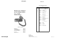
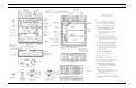
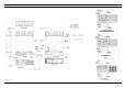
The location and placement of system hardware options
are shown on Sheet 4 of the 800 MHz Dual Format MDX
Mobile Interconnect Diagrams.
OPTION CABLE
Option Cable Option PMCD7Z (19C851585P14) is
used to bring all option connections from the System Board
through the back of the radio to the outside. This cable is
required with all external options.
NOISE SUPPRESSION KIT OPTION
Noise Suppression Kit Option PMPD1A (consisting of
Filter 19A148539G1 and Installation Manual LBI-31363) is
available for installations where excessive alternator or elec-
trical noises, present on the power cable, do not permit the
radio to operate properly. Refer to the interconnect diagram
for the radio and options.
POWER CABLE OPTION
18-foot Power Cable Option PMCD9A,
(19B801358P17), is available for installations requiring
more than the standard 9-foot cable.
EXTERNAL SPEAKER OPTION
External Speaker and Cable Option PMZM1T provides
the user with a five-inch waterproof speaker in a LEXAN
housing. PMCC9M is an 18 inch interconnecting cable for
the speaker. The radio’s 10-watt amplifier drives the
speaker’s 4-ohm impedance. The speaker leads are con-
nected to pins 2 and 9 of Option Cable Option PMCD7Z
(19C851585P14), using External Speaker Cable Option
PMCC9M (19A149590P8) (18 inches) included in the
PMZM5T kit. A 16-foot cable, Option PMCD1W
(19A149590P10) is also available.
EXTERNAL ALARM
External Alarm Horn Relay Option PMSU1C
(19A705499P1) can sound the vehicle horn when a call is
received. The option connects to pin 13 of Option Cable
Option PMCD7Z (19C851585P14) and is controlled by a
front panel option switch.
SYSTEM DESCRIPTION
EDACS
The Dual Format MDX mobile radio operates in either
EDACS (digital) mode, or in GE-MARC (tone) mode, pro-
viding customers another dimension of flexibility in opera-
tion. Both modes provide opportunities to increase RF
channel utilization through faster channel access and the
privacy inherent with selective signalling.
The EDACS system uses 9600 baud, high speed, digital
signalling to identify individual units, user groups, fleets,
and agencies. Agencies contain multiple fleets and fleets
contain multiple user groups (sub-fleets). By using this ad-
dressing scheme, large user groups can be accessed simulta-
neously all the way down to individual users. The
programming to determine transmit encoded groups and
decoded received groups is contained in the personality
EEPROM of the mobile. This information is individually
programmed to suit each users needs via the PC programmer
for the radio.
The typical system configuration consists of at least 2
repeater stations (with a maximum number of 25) and the
associated mobiles. One repeater always is a control channel
dedicated to sending out continuous control data and also to
receive channel request data from the mobiles. When a
mobile is first turned on, it scans the available list of frequen-
cies programmed in the personality EEPROM for a control
channel. When a control channel is found, the mobile locks
on to the frequency and monitors the data for a channel
assignment (incoming call).
When receiving a channel assignment (incoming call),
the monitoring mobile immediately switches over to the
assigned voice channel and waits for a high speed data
confirmation message. Upon receipt of this message, the
voice paths are unmuted and the user can hear the call.
While on the voice channel, the mobile also continu-
ously monitors the low speed, 150 baud (subaudible) data
and carrier noise squelch to ensure consistent operation.
Upon loss of subaudible data reception (i.e., deep fade, or
out-of-range), the mobile returns to the control channel
frequency.
To initiate a call, the user keys the radio (which is locked
to the control channel), and a 30 millisecond high speed data
slotted channel request is transmitted to the control channel
receiver. The control channel processes the request from the
mobile and transmits back a voice channel assignment on an
unused channel.
When all available voice channels are in use, the control
channel places the mobile into a queue, transmits a queue
message back to the mobile, and will give a channel assign-
ment to the requesting mobile as soon as a voice channel is
free. If the system is busy and the station queue is filled to
capacity, a system busy message is returned to the requesting
mobile and an alert signal is given to the user.
After the initiating mobile receives a channel assignment
from the control station, it immediately switches frequency
over to the assigned voice channel and sends a burst of 9600
baud dotting. The microphone voice paths are then unmuted
and the transmission begins. The transmitting mobile also
continuously sends out a subaudible tone (along with voice)
for system reliability. If the station loses this signalling, the
voice channel is muted and all receiving mobiles are sent back
to the control channel.
In normal operation, the transmitting mobile sends a high
speed data burst to indicate that the user has unkeyed, causing
all listening mobiles to switch back to the control channel.
CONVENTIONAL MODE
In conventional mode (not trunked) the radio can operate
either with tone Channel Guard, digital Channel Guard, or
carrier squelch, depending on personality programming. Tone
Channel Guard range is 67.0 to 210.7 Hz. Squelch Tail Elimi-
nation (STE) is used with Channel Guard to eliminate squelch
tails at the receiving radio by phase shifting the transmitted
Channel Guard tone when the PTT is released.
Direct mode works identically to conventional mode ex-
cept that the transmit frequency band is changed to 851 to 870
MHz to permit direct mobile-to-mobile communications.
GE-MARC
The
GE-MARC
trunked mobile radio system consists of
a repeater for each channel and the users’ mobile radio units.
The system uses tone signalling with each mobile being as-
signed two and/or four tone group tone sequences. Groups of
mobiles are assigned the same tones so that any unit can talk
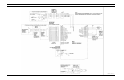
to all other units in the same group. A block diagram of the
GE-MARC MDX
is shown in Figure 1.
When originating a call, the mobile identifies an idle
repeater channel and interrogates it with a single burst of
"busy"
tone; the repeater keys its transmitter and sends a burst
of
"acquisition"
tone back to the mobile unit. When the
interrogating mobile detects the acquisition tone, it then trans-
mits its collect and group tones which the repeater regenerates
for all idle mobile units in the system.
The idle mobiles, which continually scan all channels, will
stop on the active channel if any of the programmed collect
tones are detected and wait for group tone(s).
If the correct tone sequence is detected, the mobiles will
alert the operator of an incoming call and open their audio
circuits. If the correct sequence is not detected, the idle mobiles
will resume scanning the channels. Once the mobile is
"locked"
on a channel, it will remain there until the repeater
times out or the operator terminates the call.
Operational Modes
The radio will always be in one of three operational modes:
Idle, Wait, or Ready. The three operational modes and the
conditions that cause the radio to switch from one mode to
another are shown in Figure 2.
The radio enters the Idle mode when power is turned on
and begins scanning channels for incoming calls. The Wait
mode is entered when the user places a call. The radio remains
in the Wait mode until a channel is acquired, or if no channel
is available. The Ready or Conversation mode is indicated by
an alert tone and the mode indicator on the control panel. A
signal timing diagram is shown in Figure 3.
Idle Mode
When the radio is in the Idle mode, the audio is muted and
all channels programmed for call decode are sequentially
scanned for an incoming call. An incoming call is identified by
detecting one of the collect tones programmed in the area.
Upon receipt of a collect tone, the mobile looks for a short
interval for the group or individual tones providing that their
collect tones are the same. When no valid tone is found, the
mobile will resume scanning the channels for an incoming call.
If a group (or individual decode) tone is detected, the
mobile then looks for busy tone for a 90 millisecond period. If
four tones are properly decoded, the mobile will then look for
busy tone for 270 milliseconds.
When no valid tones are found, the mobile will resume
scanning for a call with the next channel. When a busy tone is
found, the mobile will enter the Ready mode. If busy tone is
not detected, the mobile remains in the Idle mode and continues
scanning channels looking for an incoming call.
Removing the handset from the hanger, pressing the PTT
switch or pressing the SEND key on the handset will cause the
radio to enter the Wait mode.
Wait Mode
When the user enters the Wait mode, the display group is
checked to make sure it is a valid call-originate group. If it is
not valid, a low-frequency tone is heard for one second. If valid,
the radio will scan the call-originate frequencies for brief
intervals until it finds one with no busy tone on it. If no channel
is free, the radio, if programmed for this option, will activate
the Call Retry state and display "
RETRYING
" in the display.
Retrying will cause the radio to revert to the Idle mode and scan
for an incoming call while trying to acquire a free repeater
approximately every 5 seconds for a 2 minute period. If the
Retry option is not enabled, the mobile will sound the low-fre-
quency tone and then return to the Idle mode and display
"BUSY".
If a channel with no busy tone is found, the mobile trans-
mits a burst of busy tone to acquire the repeater. The repeater
then responds with a burst of acquisition tone. Upon receipt of
the acquisition tone, the mobile proceeds to transmit the group
tones (either two or four tones). If a four-tone sequence is sent,
the mobile must detect all four tones and busy tone before
entering the Ready mode. If a two-tone sequence is sent, the
busy tone must be present within 90 milliseconds of the last
LBI-38848D
4