LBI-38377E Operator’s Manual M-PA SERIES PORTABLE RADIO
NOTICE! This manual covers Ericsson and General Electric products manufactured and sold by Ericsson Inc. NOTICE! The software contained in this device is copyrighted by Ericsson Inc. Unpublished rights are reserved under the copyright laws of the United States. This manual is published by Ericsson Inc., without any warranty.
TABLE OF CONTENTS INTRODUCTION . . . . . . . . . . . . CONTROLS . . . . . . . . . . . . . . . INDICATORS . . . . . . . . . . . . . . UNIVERSAL DEVICE CONNECTOR . . ALERT TONES . . . . . . . . . . . . . OPERATION . . . . . . . . . . . . . . POWER-UP . . . . . . . . . . . . . MODE/CHANNEL/CG SELECTION RECEIVING A MESSAGE . . . . . TRANSMITTING A MESSAGE . . . EMERGENCY OPERATION . . . . SCANNING CHANNELS . . . . . . TELEPHONE INTERCONNECT CALLS . . . . . . . . . . . . . . . "KEY LOCK" MENU . . . . . . . .
PRODUCT SPECIFICATION FOR CE MARKED EQUIPMENT The M-PA Portable conforms to the following Product Specifications. EUROPEAN STANDARDS: Safety: EMC: TTD: 4 Not Applicable prETS 300 279 (August 1995) Not Applicable SUPPLEMENTARY INFORMATION: At this time, the M-PA portable radio may not be operated while in a vehicular charger in the European Community since it has not been evaluated for operation in this mode. This M-PA portable radio may be used in both trunked and conventional applications.
INTRODUCTION This manual describes the operation of the M-PA two-way FM Select, Scan, and System model portable radios. Operating controls on the radio include a rotatable control knob, rotatable volume control, a 4button keypad (Scan model) or 16-button keypad (System model), push-to-talk, emergency and monitor buttons. The on/off power switch for the unit is located on the removable battery pack.
the operating channel, mode, or specific Channel Guard encode/decode tones. See MODE/CHANNEL/CG SELECTION for details. A stop plate may be installed under the knob to limit the maximum number of positions to less than sixteen (16). It is normally factory installed for fifteen (15) positions. Some radios may be programmed with this knob disabled. "CG" and/or "T99" will turn on.
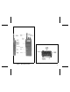
Figure 1 - M-PA Personal Radio Figure 2 - M-PA Radio (Top View) 7
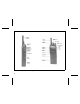
SIDE VIEW FRONT VIEW Figure 3 - M-PA Scan Model Radio 8
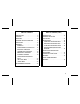
MENU BUTTON (Scan Model) Pressing the MENU button causes the radio to scroll through up to six (6) different menus programmed into the radio. After the desired menu is displayed, the feature within the menu is selected with the SEL button. The menus that may be programmed are: Menu Display Function Or Use "CHANNEL" The MENU and SEL buttons are programmed for channel selection. When this display appears, select the desired channel with the SEL button and then press EXIT.
After the menu is chosen, the desired function or feature is selected by pressing the SEL button. For example, to disable the alert tones, press MENU until "ALERT" is displayed then press SEL to select "DISABLED". Next press the EXIT button. EXIT BUTTON Pressing the EXIT button will cause the radio to exit the current menu display and return operation to the channel currently selected.
SIDE VIEW FRONT VIEW Figure 5 - M-PA System Model Radio 11
"KEY LOCK" Allows the keypad buttons to be locked or unlocked. "SCAN A/D" Allows channels to be added to or deleted from the scan list for the current mode. The priorityone channel and the priority-two channel are also set within this menu. "ALERT" Allows the alert tones to be disabled or enabled. "PHN EDIT" Allows editing of the telephone phone numbers programmed into the radio.
mode must be enabled and the desired menu must be chosen by pressing and releasing the MENU button until the desired menu appears in the display. After the menu is chosen, the desired function or feature is selected by pressing the SEL button. For example, to disable the alert tones, press MENU until "ALERT" is displayed then press SEL to select "DISABLED". Next press the EXIT button. LCD backlighting will turn on for a short period anytime an active button is pressed or the CONTROL KNOB is rotated.
T99 TX Type 99 tone decode - On indicates Type 99 tone decoding is enabled on the selected channel. Flashing indicates a T99 selective call has been received and the radio must be reset to receive another T99 call. Transmitter enabled - On when the radio is transmitting. BSY BuSY - On indicates a carrier is being received (the channel is busy).
ALERT TONES The M-PA uses alert tones or "beeps" to indicate various operating conditions. Alert tones may be enabled or disabled via the menu mode if the "ALERT" feature is programmed. See "ALERT" MENU for details. The alert tones may be disabled when the radio is programmed. TON is pressed. This feature is programmable on or off on a per channel basis. RECEIVE ONLY CHANNEL If the selected channel is programmed as receive only, the radio will sound an alert tone if a transmission is attempted.
If programmed on, the power-up alert tone (beep) will be heard. MODE/CHANNEL/CG SELECTION The M-PA Scan and System model radios may be programmed with up to 192 different radio channels. A maximum of 12 modes of 16 channels each or 16 modes of 12 channels each may be programmed into the radio (12 x 16 = 192).
2. Press the SEL button until the desired mode’s name appears in the display. 3. Press the MENU button until "CHANNEL" appears in the display. 4. Press the SEL button until the desired channel’s name appears in the display. 5. Press the EXIT button to switch radio operation to the new mode and channel, and exit the menu. 6. Select the desired Channel Guard using the CONTROL KNOB. The "CG" status flag will turn on if the selected position has CG programmed.
TRANSMITTING A MESSAGE 1. Select the desired mode, channel, and/or Channel Guard. See the MODE/CHANNEL/CG SELECTION for details.. 2. Ensure no one is transmitting on the selected channel by pressing the MONITOR BUTTON to disable squelch or observing the display for the absence of the "BSY" status flag. If the Channel Busy Lockout feature is programmed for the selected channel, the radio will not transmit when the channel is busy. 3. Press and hold the PTT BUTTON.
CONTROL KNOB will not change channels. Turning the radio off and back on will reset this condition. • GE-STAR is sent on the selected channel and the radio locks onto that channel. Rotating the CONTROL KNOB will not change channels. Turning the radio off and then back on will reset this condition. SCANNING CHANNELS (Scan and System models) The M-PA may be programmed for non-priority scan, dual-priority scan, or scan operation may be disabled.
channel. One of the following messages may be momentarily displayed: TELEPHONE INTERCONNECT CALLS SCAN Model "SCAN DIS" - – The radio is not programmed to scan. "FIXED P1" - – A priority-one channel has been programmed into the radio. A new priority-one channel can not be selected. "FIXD LST" - – A fixed scan list is pro- grammed into the radio. It is not possible to change the list without reprogramming the radio. 4. To add or delete additional channels, repeat steps 2 through 4. 5.
1. If the "SCN" status flag is on, press SCAN to turn scan off. 2. Select a channel in your radio system that has telephone interconnect capability. The radio should be programmed for DTMF operation on this channel. 3. Press the MENU button until "PHONE" appears in the display. 4. Press the SEL button to scroll through the phone list until the programmed name for the desired telephone number appears in the display. 5. Press and release the PTT BUTTON to automatically dial the selected number. 6.
TELEPHONE INTERCONNECT CALLS SYSTEM MODELS Telephone interconnect calls can be placed on radio channels equipped with this capability. Each channel programmed into the radio can be programmed for telephone interconnect by enabling it for DTMF dial operation. One (1) of the ten (10) programmed telephone numbers can be selected and automatically dialled. Communication takes place in a simplex mode.
4. While holding the PTT BUTTON, press either the " " button or the "#" button as required by the radio system to obtain a telephone line. The radio will transmit the selected tone. * 5. Release the PTT BUTTON and listen for a dial tone. 6. When the dial tone is received, press an hold the PTT BUTTON and dial the desired telephone number. As you dial each number, the DTMF sidetone will be heard in the speaker as the radio transmits the DTMF tone. 7.
4. Press the SEL button to scroll through the phone list until the programmed or stored name for the desired telephone number appears in the display. 5. Press and release the PTT BUTTON to automatically dial the selected number. 6. When the called party answers, press the PTT BUTTON to transmit and release it to receive. Repeat as needed. 7. At the completion of the call, press the EXIT button. The radio will then transmit the disconnect digit to hang-up.
3. Press the SEL button until "LOCKED" is displayed. 2. Press the MENU button until "ALERT" appears in the display. 4. To lock the keypad press the EXIT button. 3. Press the SEL button until "DISABLED" is displayed. 4. To disable the tones press the EXIT button. Unlock The Keypad 1. Press the MENU button until "KEY LOCK" appears in the display. Enable The Alert Tones 2. Press the SEL button until "UNLOCKED" is displayed. 1. Press the MENU button until "ALERT" appears in the display. 3.
PROGRAMMABLE BY CHANNEL 26 RADIO PROGRAMMABLE • Transmit and Receive Frequencies • Minimum Volume Level • 8-Character Alphanumeric Display (Channel Designator) • GE-STAR Lanyard • • Emergency Channel Tone or Digital Channel Guard Encode/Decode • Vehicular Charger Backlight • Type 99 Tone Decode • • Control Knob Selects Channels, Modes or Channel Guard Transmit Power Level High or Low • • Mode Control (Scan or System Radio) Transmit STE On or Off • • Menu Selections (Scan or Syst
OPERATING TIPS OPERATING RULES AND REGULATIONS Antenna location and condition is important when operating a portable radio. Operating the radio in low areas of terrain, under power lines or bridges, inside of a vehicle or in a metal or steel framed building can severely reduce the range of the unit. Mountains and buildings can also reduce the range of the unit. Two-way FM radio systems must be operated in accordance with the rules and regulations of the Federal Communications Commission (FCC).
2. The use of profane or obscene language is prohibited by Federal law. 3. It is against the law to send false call letters, or false distress or emergency messages. 4. call letters. Refer to the rules that apply to your particular type of operation for the proper procedure. 8. The FCC requires that you keep conversations brief and confine them to business. To save time, use coded messages whenever possible.
Figure 8 - Installing the Battery Pack REMOVING THE BATTERY PACK 1. Ensure the ON/OFF SWITCH on the battery pack is in the off position. 2. Press down on the battery release latch and slide the battery pack out in the direction of the release latch. See Figure 9. Figure 9 - Removing the Battery Pack CHARGING THE BATTERY PACKS After receiving a new rechargeable battery pack from the factory, it should be fully charged before placing it into service.
Chargers are available with nominal charge times of 1 hour (rapid) and 14 hours (standard). Combinations include single (1) and multi (5) position, standard and rapid charge units. In addition, the vehicular chargers/repeaters simultaneously charge the battery packs while the radio is operating. For specific instructions refer to the applicable charger Operating Manual. The rechargeable batteries used with the radio can develop a reduced capacity condition sometimes called the "Memory Effect".
D, E, F and G atmospheres. Non-Incendive approval includes Class I, Division 2 hazardous locations in the presence of Groups A, B, C, and D atmospheres. Hazardous locations are defined in the National Electrical Code. Useful standards NFPA 437A and NFPA 437M for the classifications of hazardous areas may be ordered from the National Fire Protection Association, Batterymarch Park, Quincy, MA 02269.
ACCESSORIES • PANC1N Antenna, 440 - 512 MHz, Whip The following accessories are approved for use with intrinsically safe radios. Use of accessories other than those listed voids Factory Mutual approval.
WARRANTY A. Ericsson Inc. (hereinafter "Seller") warrants to the original purchaser for use (hereinafter "Buyer") that Equipment manufactured by Seller shall be free from defects in material, workmanship and title, and shall conform to its published specifications. With respect to any Equipment not manufactured by Seller (except for integral parts of Seller’s Equipment to which the warranties set forth above shall apply).
NICKEL-CADMIUM BATTERY WARRANTY A. B. C. D. E. Ericsson Inc. (hereinafter "Seller") warrants to the original purchaser for use (hereinafter "Buyer") that nickel-cadmium batteries supplied by Seller shall be free from defects in material and workmanship, and shall conform to its published specifications for a period of twelve (12) months from the date of purchase.
NOTES 35
EMERGENCY NUMBERS Police State Police Fire Poison Control Ambulance Life Saving and Rescue Squad Ericsson Inc. Private Radio Systems Mountain View Road Lynchburg, Virginia 24502 1-800-592-7711 (Outside USA, 804-592-7711) Printed in U.S.A.