LBI-38901 Mobile Communications ORION MOBILE RADIO Installation Manual Printed in U.S.A.
TABLE OF CONTENTS INTRODUCTION............................................................................ 3 UNPACKING AND CHECKING EQUIPMENT ............................. 3 PLANNING THE INSTALLATION................................................ 6 EQUIPMENT REQUIRED .............................................................. 8 INSTALLATION IN VEHICLES POWERED BY LIQUEFIED (LP) GAS......................................................................................... 9 INSTALLATION....................
10. Recheck all connections and cables. Insert fuse into transmit fuse assembly. INTRODUCTION This manual contains installation instructions for the Orion Mobile Radio Unit and associated accessories. These instructions cover the mounting and cabling of the radio; interconnection and wiring diagrams are provided for reference.
8. Connect the extended option accessory plug P4 to the following options (if used, see Figure 29): • • • • • • • Mobile Data Terminal Public Address (External Amplifier) External Microphone External Tone Encoder External Tone Decoder Output (User Defined) Input (User Defined) CAUTION Refer to accessory manual supplement for details regarding the extended options listed above. DO NOT CONNECT DIRECTLY TO A PC OR DATA TERMINAL.
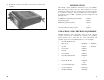
Figure 3 - Cables Figure 29 - Cassette Assembly Schematic Diagram 32 5
Table 1 - Orion Mobile Radio Optional Accessories Option D2AN1M D2AN1L D2AN1R D2CE1V D2CE1W D2CE1X D2CE1Y D2CE1Z D2CE5R D2CE5S D2CE5T D2CE5U D2CE5V D2CE5W D2CE5Z D2CE7A D2CE7B D2CE7C D2LS1F D2LS1H D2MA3J D2MA3N D2MA3R D2MA3W D2MA3X D2MC3W D2MC3Z D2MK3E D2MK3F D2MN1A D2PD1J Description 900 MHz, 1/4 Wave Whip Antenna 800 MHz 1/4 Wave Whip Antenna VHF/UHF, 1/4 Wave Whip Antenna Power Cable, 7.5 M Accessory Cable, Front Mount Accessory Cable, Rear Mount Control Cable, Remote Mount, 5.
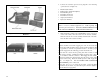
Top Mount Figure 4 - Typical Installation (Remote Mount Shown) Bottom Mount Figure 27 - Remote Mounting Bracket Installation Cassette Mounting (EURO ONLY) The cassette mounting assembly is designed to mount in a standard DIN space in the instrument panel or console. This mounting permits rapid insertion and removal of the radio unit from the vehicle. All connections are made through a quick disconnect connector at the rear of the cassette mounting assembly to the radio unit.
EQUIPMENT REQUIRED Remote Mount Installation • Crimping Tool for fuse holder The bracket shown in Figure 27 is used for Remote Mounting (USA Only). In some applications the bracket shown in Figure 26 can also be used for Remote Mounting. The following instructions are for a Remote Mount installation using the bracket shown in Figure 27. • Electric drill for drilling mounting holes 1.
INSTALLATION IN VEHICLES POWERED BY LIQUEFIED (LP) GAS Radio installation in vehicles powered by liquefied petroleum gas with the LP gas container in the trunk or other sealed-off space within the interior of the vehicle must conform to the National Fire Protection Association Standard NFPA 58 which requires that: Top Mount • Space containing radio equipment shall be isolated by a seal from the space containing the LP gas container and its fittings.
Figure 5 - Front Mount Basic Accessory Interconnections (USA Models Only) Figure 25 - Speaker Mounting RADIO MOUNTING AND FINAL HOOK-UP Front Mount Figure 6 - Front Mount Basic Accessory Interconnections (EURO Models Only) Figure 7 - Front Mount Extended Option Accessory Interconnections (USA Models Only) 10 Typically the bracket shown in Figure 26 is used for Front Mount applications. The bracket can be mounted so that it is either above or below the radio for the user's convenience.
Top Mount Bottom Mount Figure 8 - Front Mount Extended Option Accessory Interconnections (EURO Models Only) Figure 24 - Control Unit Mounting Bracket Installation SPEAKER D2LS1F The speaker kit includes the speaker, mounting bracket and connecting cable. Mount the speaker so it is directed to the operator but does not present a hazard in the event of an accident. The speaker may be mounted on the lower edge of the instrument panel, the firewall or above the windshield in some trucks. 1. 2.
Figure 11 - Remote Mount Extended Option Accessory Interconnections (USA Models Only) Figure 12 - Remote Mount Extended Option Accessory Interconnections (EURO Models Only) Power Cable The USA power cable (19B802622P1) consists of a red lead A+ and a black lead A- connected to a molded 2-pin power connector and terminated with ring terminals.
3. Cut off 12-18 inches from the red lead. Strip back the insulation approximately 3/8 of an inch on each end of the wires. Pull the wire ends through the small openings at the end of each fuse holder section and crimp a fuse connector to each wire. Connect the other end of the short wire to the positive (+) terminal of the battery. NOTE Do not install fuse into fuse holder until installation is completed and all connections have been checked.
Figure 14 - USA Front Mount Standard Accessory Cable 19B802554P1 14 Figure 21 - EURO Remote Control Cable 19B802554P4 23
Figure 20 - USA Remote Control Cable 19B802554P3 22 Figure 15 - EURO Front Mount Standard Accessory Cable 19B802554P11 15
CAUTION Certain problems may be encountered when accessory equipment is connected to the ignition or accessory lines of the vehicle, where these lines may have large filter capacitors and a leakage path present. If the radio does not turn off within a reasonable amount of time after the ignition is turned off, first try a different accessory or ignition sense pick up point in the vehicle.
Ignition Sense (All Applications) NOTE • The radio as shipped from the factory has the "ignition sense" feature disabled. As such the radio will be powered ON or OFF as determined by the front panel ON/OFF/VOLUME control only (assuming A+ and A- are connected). If it is desired to enable the "ignition sense" feature, open top cover of radio and remove shield from logic PWB. Slide switch SW601 from position 3-2 to 1-2. Replace shield and top cover.
Remote Mount The Basic Accessory Cable, at one end, consists of the basic accessories connector (P3) and the speaker connector (P2). At the other end is the plug P1. P1 will connect to the Option Connector (OPT) which is mounted on the back of the Radio Interface Adapter (RIA). The Extended Option Accessory Cable is the same as the Basic Cable but with the addition of the Extended Option Plug (P4). See Figures 18 and 19.
Remote Mount The Basic Accessory Cable, at one end, consists of the basic accessories connector (P3) and the speaker connector (P2). At the other end is the plug P1. P1 will connect to the Option Connector (OPT) which is mounted on the back of the Radio Interface Adapter (RIA). The Extended Option Accessory Cable is the same as the Basic Cable but with the addition of the Extended Option Plug (P4). See Figures 18 and 19.
Ignition Sense (All Applications) NOTE • The radio as shipped from the factory has the "ignition sense" feature disabled. As such the radio will be powered ON or OFF as determined by the front panel ON/OFF/VOLUME control only (assuming A+ and A- are connected). If it is desired to enable the "ignition sense" feature, open top cover of radio and remove shield from logic PWB. Slide switch SW601 from position 3-2 to 1-2. Replace shield and top cover.
CAUTION Certain problems may be encountered when accessory equipment is connected to the ignition or accessory lines of the vehicle, where these lines may have large filter capacitors and a leakage path present. If the radio does not turn off within a reasonable amount of time after the ignition is turned off, first try a different accessory or ignition sense pick up point in the vehicle.
Figure 20 - USA Remote Control Cable 19B802554P3 22 Figure 15 - EURO Front Mount Standard Accessory Cable 19B802554P11 15
Figure 14 - USA Front Mount Standard Accessory Cable 19B802554P1 14 Figure 21 - EURO Remote Control Cable 19B802554P4 23
3. Cut off 12-18 inches from the red lead. Strip back the insulation approximately 3/8 of an inch on each end of the wires. Pull the wire ends through the small openings at the end of each fuse holder section and crimp a fuse connector to each wire. Connect the other end of the short wire to the positive (+) terminal of the battery. NOTE Do not install fuse into fuse holder until installation is completed and all connections have been checked.
Figure 11 - Remote Mount Extended Option Accessory Interconnections (USA Models Only) Figure 12 - Remote Mount Extended Option Accessory Interconnections (EURO Models Only) Power Cable The USA power cable (19B802622P1) consists of a red lead A+ and a black lead A- connected to a molded 2-pin power connector and terminated with ring terminals.
Top Mount Bottom Mount Figure 8 - Front Mount Extended Option Accessory Interconnections (EURO Models Only) Figure 24 - Control Unit Mounting Bracket Installation SPEAKER D2LS1F The speaker kit includes the speaker, mounting bracket and connecting cable. Mount the speaker so it is directed to the operator but does not present a hazard in the event of an accident. The speaker may be mounted on the lower edge of the instrument panel, the firewall or above the windshield in some trucks. 1. 2.
Figure 5 - Front Mount Basic Accessory Interconnections (USA Models Only) Figure 25 - Speaker Mounting RADIO MOUNTING AND FINAL HOOK-UP Front Mount Figure 6 - Front Mount Basic Accessory Interconnections (EURO Models Only) Figure 7 - Front Mount Extended Option Accessory Interconnections (USA Models Only) 10 Typically the bracket shown in Figure 26 is used for Front Mount applications. The bracket can be mounted so that it is either above or below the radio for the user's convenience.
INSTALLATION IN VEHICLES POWERED BY LIQUEFIED (LP) GAS Radio installation in vehicles powered by liquefied petroleum gas with the LP gas container in the trunk or other sealed-off space within the interior of the vehicle must conform to the National Fire Protection Association Standard NFPA 58 which requires that: Top Mount • Space containing radio equipment shall be isolated by a seal from the space containing the LP gas container and its fittings.
EQUIPMENT REQUIRED Remote Mount Installation • Crimping Tool for fuse holder The bracket shown in Figure 27 is used for Remote Mounting (USA Only). In some applications the bracket shown in Figure 26 can also be used for Remote Mounting. The following instructions are for a Remote Mount installation using the bracket shown in Figure 27. • Electric drill for drilling mounting holes 1.
Top Mount Figure 4 - Typical Installation (Remote Mount Shown) Bottom Mount Figure 27 - Remote Mounting Bracket Installation Cassette Mounting (EURO ONLY) The cassette mounting assembly is designed to mount in a standard DIN space in the instrument panel or console. This mounting permits rapid insertion and removal of the radio unit from the vehicle. All connections are made through a quick disconnect connector at the rear of the cassette mounting assembly to the radio unit.
Table 1 - Orion Mobile Radio Optional Accessories Option D2AN1M D2AN1L D2AN1R D2CE1V D2CE1W D2CE1X D2CE1Y D2CE1Z D2CE5R D2CE5S D2CE5T D2CE5U D2CE5V D2CE5W D2CE5Z D2CE7A D2CE7B D2CE7C D2LS1F D2LS1H D2MA3J D2MA3N D2MA3R D2MA3W D2MA3X D2MC3W D2MC3Z D2MK3E D2MK3F D2MN1A D2PD1J Description 900 MHz, 1/4 Wave Whip Antenna 800 MHz 1/4 Wave Whip Antenna VHF/UHF, 1/4 Wave Whip Antenna Power Cable, 7.5 M Accessory Cable, Front Mount Accessory Cable, Rear Mount Control Cable, Remote Mount, 5.
Figure 3 - Cables Figure 29 - Cassette Assembly Schematic Diagram 32 5
8. Connect the extended option accessory plug P4 to the following options (if used, see Figure 29): • • • • • • • Mobile Data Terminal Public Address (External Amplifier) External Microphone External Tone Encoder External Tone Decoder Output (User Defined) Input (User Defined) CAUTION Refer to accessory manual supplement for details regarding the extended options listed above. DO NOT CONNECT DIRECTLY TO A PC OR DATA TERMINAL.
10. Recheck all connections and cables. Insert fuse into transmit fuse assembly. INTRODUCTION This manual contains installation instructions for the Orion Mobile Radio Unit and associated accessories. These instructions cover the mounting and cabling of the radio; interconnection and wiring diagrams are provided for reference.
TABLE OF CONTENTS INTRODUCTION............................................................................ 3 UNPACKING AND CHECKING EQUIPMENT ............................. 3 PLANNING THE INSTALLATION................................................ 6 EQUIPMENT REQUIRED .............................................................. 8 INSTALLATION IN VEHICLES POWERED BY LIQUEFIED (LP) GAS......................................................................................... 9 INSTALLATION....................
LBI-38901 Mobile Communications ORION MOBILE RADIO Installation Manual Printed in U.S.A.