
Installation manual
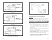
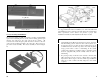
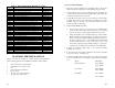
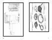
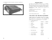
Table 1 - Orion Mobile Radio Optional Accessories
Option Description Part Number
D2AN1M 900 MHz, 1/4 Wave Whip Antenna 19B801182P3
D2AN1L 800 MHz 1/4 Wave Whip Antenna 19B209568P5
D2AN1R VHF/UHF, 1/4 Wave Whip Antenna 19B209568P6
D2CE1V Power Cable, 7.5 M 19B802622P1
D2CE1W Accessory Cable, Front Mount 19B802554P1
D2CE1X Accessory Cable, Rear Mount 19B802554P6
D2CE1Y Control Cable, Remote Mount, 5.5 M 19B802554P3
D2CE1Z Accessory Cable, Front Mount EURO 19B802554P11
D2CE5R Extended Option Accessory Cable Front Mount 19B802554P2
D2CE5S EXT Option Control Cable, Remote Mount, 5.5 M 19B802554P4
D2CE5T EXT Option Accessory Cable, Remote Mount 19B802554P7
D2CE5U EXT Option Accessory Cable, Front Mount, EURO 19B802554P12
D2CE5V Control Cable, Remote Mount, EURO, 5.5 M 19B802554P13
D2CE5W EXT Option Control Cable, Remote Mount, 5.5 M 19B802554P14
D2CE5Z Dual Control Cable, Remote Mount, 9.0 M 19B802554P9
D2CE7A Dual Radio Cable, Remote Mount, 2.0 M 19B802554P10
D2CE7B Dual Control Cable, Remote Mount, 9.0 M, EURO
D2CE7C Dual Radio Cable, Remote Mount, 2.0 M, EURO
D2LS1F Speaker, GE Label 19A149590P1
D2LS1H Speaker, ERICSSON Label 19A149590P11
D2MA3J Mounting Bracket Kit, Remote Control Unit 344A4584G2
D2MA3N Mounting Bracket Kit, Front Mount Radio 19B802672P1
D2MA3R Mounting Bracket Kit, Remote Mount Radio 19B802673P1
D2MA3W Mounting Bracket Kit, Remote Mount Radio, EURO 19B802672P1
D2MA3X Cassette Mounting Bracket Kit, Front Mount, EURO 19B852366P1
D2MC3W Microphone, GE Label
D2MC3Z Microphone, Ericsson Label
D2MK3E Keycap Kit, SCAN Control Unit 19C852359P101
D2MK3F Keycap Kit, SYSTEM Control Unit 19C852359P102
D2MN1A Microphone Hanger 7141414G2
D2PD1J Transmit Fuse Holder Kit, 20/30A (USA Only) 19A149701G2
PLANNING THE INSTALLATION
Figure 4 provides an example of a typical mobile radio installation.
Before starting, plan the radio installation carefully so that it will be:
•
safe for the operator and passengers
•
convenient for the operator to use
•
neat
•
protected from water damage
•
easy to service
•
out of the way of auto mechanics
•
out of the way of passengers
6
Cassette Assembly Mounting
1. Insert the cassette assembly in the mounting location. Secure the
cables with the sheet metal screws and retaining straps provided.
2. Secure the back of the cassette assembly using the mounting stud
(located at the back of the cassette assembly), No. 6 flat washer, No.
6 split lock washer and No. 6 wing nut.
3. Several tabs are located on the top, bottom and sides of the cassette
assembly. These tabs are conveniently located near the front of the
assembly and may be bent out as needed to further secure the
cassette assembly to the vehicle.
4. Next install the Handle Assembly:
a. Turn the radio upside down. Remove the two small machine
screws on the bottom of the radio, near the front. Use upward
pressure on screws to engage captivated threads for removal.
b. Using the machine screws and flat washers provided with the
handle assembly, attach the handle to the bottom of the radio.
The two holes on the handle should align with the two holes on
the radio created by step (a). Once installed, the rubber handle
should rotate freely from over top of the radio to just out in
front of the control unit (approximately 90 degrees). Be sure to
torque the two mounting screws within 6.5 to 8.25 in/lb limits.
5. Connect the antenna coaxial cable to the cassette mounting
assembly rear connector.
6. Connect the Power leads and the Ignition Sense leads as described
in previous sections. See Figure 29.
7. Connect the speaker cable connector P2 to the speaker and the basic
accessory connector P3 to the following options (if used, see Figure
29):
Option Plug & Pin
Ext. Hookswitch P3-3 (HOT)
P3-6 (GND)
Foot Switch P3-5 (HOT)
P3-2 (GND)
Horn Relay P3-1 (HOT)
P3-4 (GND)
31