
Operating instructions

LBI-39135
10
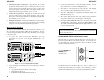
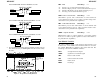
3. System/Group Knob Verification. Repositioning the system/
group knob should cause the radio to sound the key-ack tone at the
current volume level and display the knob position on the bottom
level of the display. The bottom line of the display returns to the
full pixel display after approximately one (1) second.
4. Volume Knob Verification. Changing the Volume knob should
cause the volume level to change and be displayed on the top line.
The top line of the display will return to the full pixel display after
approximately one (1) second.
5. Backlight Verification. Pressing the PTT button, Option button,
Clear button or any key on the keypad should cause the backlight
to light up at the level indicated by the PC Programmer.
Orion Control Unit Test
The Orion Control Unit has built into the Software the capacity to test
the control unit's keypad, display, LED's, knobs and buttons. For this
reason the Diagnostic Radio Code Power-Up Test Mode does not apply
to the Orion radio.
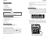
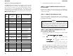
1. To Access the Orion Control Unit Test Mode, press the
appropriate two (2) keys on the keypad simultaneously. See
Figure 4.
Figure 6 - Access Control Unit Test Mode
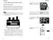
1. Upon entering the control unit test mode, the following conditions
should occur:
• copyright information should be on the display
• all keylights should be on
• the BUSY, SCAN and TX LEDs should be on
LBI-39135
11
2. Use the Up1 and Down1 to control the display intensity. Use the
Up2 and Down2 to control the backlight intensity.
3. Test the keys on the keypad by pressing each key. The keylight
above each key should extinguish as the key is pressed.
4. After all the keylights are extinguished, the BUSY, SCAN, and
TX LEDs should go out.
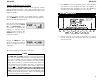
5. The volume, light intensity and rotary selector knob information
along with software version should appear on the display.
6. Pressing keys 01 and 02 will display the control unit's network ID
and RQST line configuration. Pressing the 01 and 02 keys will
also result in the Federal SS2000 siren and lights interface to send
out a two byte bit pattern.
In the control unit test mode, the control unit will not communicate
with any network devices.
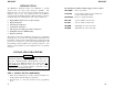
RADIO OPERATION (M-RK Radios Only)
When the radio is powered up with the diagnostic code, the radio is in
the Power-Up Test Mode as described previously. To exit the Power-
Up Test Mode and enter the Diagnostic Test Load Mode (normal
operation with limited features):
press the OPTION and
CLEAR buttons
simultaneously
The Diagnostic Test Load Mode allows the radio to function as a
normal radio with a limited set of features. The following is a list of
enabled and disabled features for Conventional and Trunked systems.
NOTE