UM10067 ISP1760; ISP1761 Windows CE 5.0 user installation guide Rev. 03 — 12 October 2009 User manual Document information Info Content Keywords usb; universal serial bus; isp1760; isp1761 Abstract This document describes the Platform Builder setup for the ISP176x Universal Serial Bus (USB) Host Controller Driver. The document covers the installation of software for the ISP176x on the Microsoft Windows CE platform version 5.0.
UM10067 ISP1760; ISP1761 Win CE 5.0 User Installation Guide Revision history Rev Date Description 03 20091012 Rebranded to the ST-Ericsson template. 02 20090216 Rebranded to the ST-NXP Wireless template. 01 20051018 First release. Contact information For additional information, please visit: http://www.stericsson.com For document related queries, please send an email to: wired.support@stericsson.com UM10067_3 User manual © ST-ERICSSON. All rights reserved. Rev.
UM10067 ISP1760; ISP1761 Win CE 5.0 User Installation Guide Remark: The ISP176x denotes the ISP1760 and ISP1761 Hi-Speed Universal Serial Bus controllers, and any future derivative. 1. Introduction This document describes the Platform Builder setup for the ISP176x Universal Serial Bus (USB) Host Controller Driver (HCD). The document covers the installation of software for the ISP176x on the Microsoft Windows CE platform Ver. 5.0. The software architecture supports the PCI and GPIO bus.
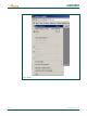
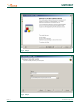
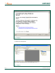
UM10067 ISP1760; ISP1761 Win CE 5.0 User Installation Guide Fig 1. Step 1. UM10067_3 User manual © ST-ERICSSON. All rights reserved. Rev.
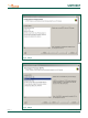
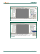
UM10067 ISP1760; ISP1761 Win CE 5.0 User Installation Guide Fig 2. Step 2. Fig 3. Step 3. UM10067_3 User manual © ST-ERICSSON. All rights reserved. Rev.
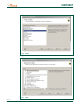
UM10067 ISP1760; ISP1761 Win CE 5.0 User Installation Guide Fig 4. Step 4. Fig 5. Step 5. UM10067_3 User manual © ST-ERICSSON. All rights reserved. Rev.
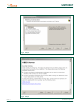
UM10067 ISP1760; ISP1761 Win CE 5.0 User Installation Guide Fig 6. Step 6. Fig 7. Step 7. UM10067_3 User manual © ST-ERICSSON. All rights reserved. Rev.
UM10067 ISP1760; ISP1761 Win CE 5.0 User Installation Guide Fig 8. Step 8. Fig 9. Step 9. UM10067_3 User manual © ST-ERICSSON. All rights reserved. Rev.
UM10067 ISP1760; ISP1761 Win CE 5.0 User Installation Guide Fig 10. Step 10. 3. Refresh the catalog items. Fig 11. Step 11. UM10067_3 User manual © ST-ERICSSON. All rights reserved. Rev.
UM10067 ISP1760; ISP1761 Win CE 5.0 User Installation Guide Fig 12. Step 12. Fig 13. Step 13. UM10067_3 User manual © ST-ERICSSON. All rights reserved. Rev.
UM10067 ISP1760; ISP1761 Win CE 5.0 User Installation Guide Fig 14. Step 14. Fig 15. Step 15. UM10067_3 User manual © ST-ERICSSON. All rights reserved. Rev.
UM10067 ISP1760; ISP1761 Win CE 5.0 User Installation Guide Fig 16. Step 16. Fig 17. Step 17. UM10067_3 User manual © ST-ERICSSON. All rights reserved. Rev.
UM10067 ISP1760; ISP1761 Win CE 5.0 User Installation Guide Fig 18. Step 18. Fig 19. Step 19. UM10067_3 User manual © ST-ERICSSON. All rights reserved. Rev.
UM10067 ISP1760; ISP1761 Win CE 5.0 User Installation Guide Fig 20. Step 20. Fig 21. Step 21. Fig 22. Step 22. UM10067_3 User manual © ST-ERICSSON. All rights reserved. Rev.
UM10067 ISP1760; ISP1761 Win CE 5.0 User Installation Guide 4. Adding the ISP176x project to the platform In this section, you will learn to add the ISP176x Host Controller catalog items to the operating system design view. It is assumed that the platform is already created and the ISP176x catalog files have been imported. If you are working on the PCI bus, you need to add the PCI bus driver to route the PCI interrupt to the ISP176x. If you are using the GPIO bus, you can ignore this step.
UM10067 ISP1760; ISP1761 Win CE 5.0 User Installation Guide Fig 24. Adding the component: ISP176x Host Controller. 5. Interfacing routines The ISP176x Host Controller module is located below Microsoft defined USBD. The ISP176x Host Controller module interacts with the ISP176x hardware located at the bottom level and with the USBD located above this module. Fig 25 shows interfacing the blocks of the ISP176x to an operating system. UM10067_3 User manual © ST-ERICSSON. All rights reserved. Rev.
UM10067 ISP1760; ISP1761 Win CE 5.0 User Installation Guide CORE USBD CLASS DRIVER AND OTHER OPERATING SYSTEM DEPENDENT UNITS ISP176x OTG CONTROLLER DRIVER OPERATING SYSTEM ISP176x HOST CONTROLLER DRIVER ISP176x PERIPHERAL CONTROLLER DRIVER OPERATING SYSTEM ISP176x HARDWARE ACCESS LAYER IO INTERFACE ISP176x HARDWARE HARDWARE ROOT HUB TT HUB WITH THREE PORTS HIGH-SPEED USB PORT HIGH-SPEED USB PORT OTG PORT Fig 25. ISP176x system interface. 6.
UM10067 ISP1760; ISP1761 Win CE 5.0 User Installation Guide 6.1 PCI bus mode The software is tested and proven on the PLX9054 bridge. PCI bridge chip PLX9054 in the ISP176x PCI kit is used for the PCI host to transparently access the ISP176x. PLX9054 requests PCI bus resources, such as I/O ports, interrupt line, on behalf of the ISP176x. PLX9054, however, can only request one interrupt line for the ISP176x. If required, customize file P1761bus.reg under WINCE500\3rdparty\STERICSSON\PhISP176xbus\.
UM10067 ISP1760; ISP1761 Win CE 5.0 User Installation Guide [HKEY_LOCAL_MACHINE\Drivers\ISP176x\Instance] "Dll"="RegEnum.dll" ; ========================================================= ; USB - ST-ERICSSON ISP176xHCD driver template ; ========================================================= [HKEY_LOCAL_MACHINE\Drivers\ISP176x\Template] "InstanceIndex"=dword:0 The driver will not be loaded, if these parameters do not match bridge settings. 6.
UM10067 ISP1760; ISP1761 Win CE 5.0 User Installation Guide To ensure that PCI bus driver PCIBus.dll loads P1761 bus driver P1761Bus.dll, porting engineer should verify that the above-mentioned registry key matches with the PLX9054 setting in the P1761bus.reg file located under directory ST-ERICSSON\PhISP176xBus. Once P1761Bus.dll is loaded and the system loads Host Controller stack P1761hcd.dll by checking registry setting in P1761bus.reg under directory STERICSSON\PhISP176xbus.
UM10067 ISP1760; ISP1761 Win CE 5.0 User Installation Guide 3. From the %ProgramFiles%\Windows CE Platform Builder\5.00\CEPB\Utilities directory, run CEPCBoot.144. You can also run CEPCBoot.144 from the command line. 4. If your floppy disk is not blank and formatted, check format before making disk box in the Web Image NT window. This causes WebSetup.exe to format the boot floppy disk with MS-DOS 6.22 before copying the CEPCBoot.144 disk image to the boot floppy disk. 5.
UM10067 ISP1760; ISP1761 Win CE 5.0 User Installation Guide Fig 28. Step 2. 3. Choose your device boot name or IP address. Fig 29. Step 3. 4. Select Attach Device to download the image to the target. UM10067_3 User manual © ST-ERICSSON. All rights reserved. Rev.
UM10067 ISP1760; ISP1761 Win CE 5.0 User Installation Guide Fig 30. Step 4. 10. References [1] Universal Serial Bus Specification Rev. 2.0 [2] ISP1760 Hi-Speed USB host controller for embedded applications data sheet [3] ISP1761 Hi-Speed USB On-The-Go controller data sheet [4] Enhanced Host Controller Interface Specification for Universal Serial Bus Rev. 1.0. 11. Glossary Table 1.
UM10067 ISP1760; ISP1761 Win CE 5.0 User Installation Guide 12. Legal information Please Read Carefully: The contents of this document are subject to change without prior notice.
UM10067 ISP1760; ISP1761 Win CE 5.0 User Installation Guide 13. Contents 1. 2. 3. 4. 5. 6. 6.1 6.2 6.3 6.4 7. 8. 9. 10. 11. 12. 13. Introduction ......................................................... 3 Installing the ISP176x host software ................. 3 ISP176x HCD Windows CE Ver. 5.0 operating system design ..................................................... 3 Adding the ISP176x project to the platform .... 15 Interfacing routines ...........................................