Mateable transfer wiring-system for connectors to DIN 41 612 and VG 95 324 1 ERNI Elektroapparate GmbH D-73099 Adelberg ++49-7166-500 � 7 27 759 Telefax: ++49-7166-50 282 -a- 1.
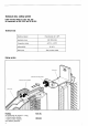
Table of contents Cable housings for connectors to DIN 41 612 and VG 95 324 General, Patterns, Packing Dimensions Technical data, Coding system Cable housings KSG 173 for connectors type B, C, D, E, H11, H15, Q, R KSG 203 for female connectors type F KSG 253 for female ribbon-cable (IDC)-connectors type C Individual parts, Ordering information Guide elements for front panel connection Guide elements for mounting through wiring field Guide elements for mounting on rear side of 19" racks andlor backplanes Gu
Cable housings KSG 173, 203,253,193 for connectors DIN 41 612 and VG 95 324 General: This cable housing family meets the demand for a fully-insulated compact housing suitable for holding either the male or female half of connectors to DIN 41 612. The mechanical protection provided by the cable housings makes these PCB-related connectors suitable for all kind of electrical interfaces. They can be used as board-towire connectors, as coding or test plugs or as plug-in jumper connections.
Dimensions Cable housing KSG 173 for male and female connectors types B, C, D, H1 1, Q, R An adaptor element is necessary for fitting types B and Q.
Gable housings KSG 173 for female connectors type H15 L-+ Cable entry 16x20 mm Cable housings KSG 203 for female connectors type F = Cable enliy 11x15 mm
Dimensions Cable housings KSG 253 for female ribbon-cable (IDC) - connectors type C Cable entries at rear and on both sides Cable entry at rear .
Dimensions Cable housings KSG 253 to carry small electronic circuits LEDs can be fitted at the rear of the cable housing for the visual indication of fault signals or switch positions.
Technical data, coding system Cable housings KSG 173, 203, 253,193 for connectors to DIN 41 612 and VG 95 324 Technical data Mouldina material 1 Application class 1 Temperature range 1 Inflammability 1 Metal parts Polycarbonate 30 % GFR 1 1 1 1 Coding system EKD DIN 40 040 -65OC to +l25OC UL 94 V-1 Steel, surface treated 1 1 1 1 a Packing As comuonent set uacked in a ban: <, 2 coding bushes positive 2 coding bushes negative and fastening elements 8 Part-No.
Individual parts, ordering details Cable housings KSG 173,203,253 for male and female connectors to DIN 41 612 Individual parts 2 3 4 5 6 7 8 Fillister headscrew M 2.5 x ...DIN 84 Guide element Blind plug Cable sleeve Fillister head screw M 2 . 5 ... ~ DIN 84 Strain relief Cable guide An adaptor element is necessary for fitting types B and 0.
Guide elements Guide elements for front panel connection with connector types B, C, D, E, F, H 11, H 15, Q, R This interface system gives users the opportunity of providing mateable connections on the front-panels. The guide elements can either be fitted as pull grips or be mounted on metal front panels.
Order details, mounting cutouts Order details for guide elements (sets) Application Part No.
Guide elements for mounting through wiring fields with connector types B, C, D, E, F, H 11, H 15, Q, R - In a similar way to front-mounted connectors, this interface Explanation Installation possibilities System also provides for making mateable interC0nne~- pas, 1 The guide elements are fitted to the motherboard tions directly from the wiring field to a printed circuit board. support.
Order details, mounting cutouts Order details for guide elements [sets) Pos. Guide element for 1 1 Male connector Female connector 1 Male connector 1 1 Mounting cutout for guide element 043 553 / Possibility of mounting the guide elements either in h i row 104.14 (hole dia. 2.6 mm) or in hole row 122,5. M 2.5 mead Part No. Type 1 1 F, H11, H15, 1 043553 1 for guide element 043 554 Possibility of mounting the guide elements either in h e row 104,14 (hole dia, 2,6 mm 0 in h i row 122.5.
Guide elements for mounting on mother boards or on printed circuit boards with connector types B, C, D, E, H 11, Q, R The interfacing technique shown in Pos. 1 is particularly suitable for cases and cabinets fitted with pivoting wiring frames. The guide elements are mounted adjacent to or on the subracks. A particular advantage of this interface system is the wide variety of wiring possibilities it offers.
Order details, mounting cutout Order details for guide elements [sets] 1 1 Pm. Guide element for l Female connector Male connector 1 Part No.
Guide frames and spacer elements for fitting in the wiring plane for use with connector types B, C, D, E, Q, R W~thth~sInterface svstem, mateable lnterconnectlons can Explanation - Installation possibilities be provided on the wiring end between the internal wiring Pos, 1 Spacer elements are secured to female connectors and the external wiring.
Order details Order details for guide frames (sets] 1 For connection to Female connectors types B, C, DUE Male connectors types Q, R Wiring elements VE 64,VE 96 Plug-on distribution strips SV 32 033 020 Femaie connectors type EUE Plug-on distribution strips SV 48 033 02l - - Female connectors type F*) Order details for spacer elements Mounting element fixed on subrack Mounting rail (2 mm thickness) Mounting in wiring plane For connection to 1 1 part NO.
Application examples Cable housing KSG 173 This cable housing is also suitable for holding electronic circuits ~~~ ~~~ .~ .-- 0 ~~~~~ .. .. ~ ~ ~~~ .. 3 T l.KSG 173 as a memory cassette, for example, for machine controls. Here 2 EPROMS are soldered together with a 32-pole male connector to a circuit board, The storage capacity in this example is 2Kx16 bit. These memories retain their data over many years without any power supply. 2. KSG 173 (3T) fitted with a pre-selector switch VS 632.
Circuit board drilling pattern for male and female connectors to DIN 41 612 with right-angled connecting pins View of equipment side 1) F H l1 48 11 abc e Even numbered 1,O 2-5-8...26-29-32 1-6 2) Hole pattern drawing for male connectors and reversed female connectors to DIN 41 612. Hole pattern drawing for female connectors with right-angled connection pins.
Cable housing KSG 193 for male and female connector types BK and CK to VG 95324 (half length VG connectors) An adaptor is necessary when fitting type BK Cableertry 11x15 mm 1 Order details Designation Number of Cable entries Type Part No. KSG 193 1 BK, CK 193001 KSG 193 2 BK, CK 193 002 Adaptor - BK 133117 Cable housings with 3 cable ei on request.
Dimensions, order details and mounting cutouts Dimensions Pos.1 Guide element for fitting male connectors (female connector in the cable housing). Pos. 2 Guide element for fitting female connectors (male connector in the cable housing). Cable housing in connected condition Order details for guide elements (sets) POS. Guide element for Type Part No.
Guide elements for mounting type BK and CK connectors (half-length VG connectors) on wiring planes A particular advantage of this method of interconnection wiring is the wide variety of wiring methods that are possible. A female connector type chosen to suit the wiring method used (wire wrapping, solder, fast-on or piggy-back connections) is fitted in the interconnection field. Thus the interconnection field and the wiring plane have identical terminations.
Order details, mounting cutout Order details for guide elements (set) Pm Guide element for Type Part No.
Guide elements for fitting with connector types BK and CK [half-length VG connectors) in the wiring plane In a similar way to front-mounted connectors, this interface system also provides for making mateable interconnections directly from the wiring end to a printed circuit board. The auide elements are mounted on the mother board and serve to locate the card in the rack Explanation The guide elements are mounted on the motherboard.
Order details, mounting cutout Order details for guide elements [sets) Pos. Guide element for Type Part No.
Circuit board drilling pattern for male and female connectors type BK and CK (half-length VG connectors) with right-angled connecting pins View of equipment side Of 1 Equipped with contac Rows occupied poles BK 32 ab Complete 1,O BK 16 ab Even numbered 1,O CK 48 abc Complete 1 ,O CK 32 a c Comolete 1n CK 1 16 1 a c 1 1) Hole pattern drawing for male connectors BK and CK to VG 95 324. 2) Hole pattern drawing for female connectors BK and CK with right-angled connecting pins.
ERN Wiring strips and plug-on distribution strips 19" subracks have space for mounting female connectors Electrical and mechanical characteristics to DIN 41 612 vertically in the wiring plane while the top and bottom edge wiring fields have room for mounting wiring strips and plug-on distribution strips horizontally. These strips are also suitable for mounting in the wiring plane.
Wiring strips Dimensions, ordering information Wiring strips VE 96-abc-0.6 x0.6 mm Wiring strips VE 64-ac-0.6 Connection pins gold-plated Part-No.: 013 401 Connection pins gold-plated Part-No.: 013 402 Wiring strips VE 32-ac-l x l mm Wiring strips VE 48-ace-l x l mm Connection pins tin-plated Part-No.: 023 801 Connection pins tin-plated Part-No.
Plug-on distribution strips Dimensions, ordering information Plug-on distribution strip SV 32-ac-l X 1/1 X 0,6 mm Plug-on distribution strip SV 48-ace-1 X 1/1 X 0,6 mm Remaining dimensions as for wiring strip VE 32-ac-1 XI Remaining dimensions as for wiring strip VE 48-ace1 XI Connection pins gold-plated Part-No.: 113 401 Connection pins gold-plated Pan-No.
Index of Part-Nos. Part-No. Page Part-No.
Notes
ERN1 Elektroapparate GmbH P.O. Box D-73099 Adel berg Phone (07166) 50-0 Fax (07166) 50119 Telex 727759 Our products: Two-part connectors to DIN 41 612 and VG 95 324, Press-fit connectors, SMD connectors, Miniature connectors with l .27mm pitch, , * E 2.