User Manual for SYSTEM 500M SYSTEM 500M User Manual - Rev. 4.
User Manual for SYSTEM 500M Operation of Adpro equipment Setting the Keyboard Access Level 18 Take Adpro control 18 Adpro functions 18 Programming the Adpro equipment 18 Operation of Integrated Camera Unit (ICU) GB - Page 2 18 19 Auto focus 19 Auto iris 19 Back Light Compensation 19 Macro playback 20 Error Messages 21 Keyboards 1500M and 1502M layouts 25 Keyboards 1501M and 1503M layouts 27 Number 2822-00025
User Manual for SYSTEM 500M Keyboard types Five different keyboard types can be used to control the SYSTEM 500M: Keyboard 1500M: Arrow keys for Pan/Tilt, no display, one shared RS232/RS485 port, no Adpro control keys, no ICU control keys Keyboard 1501M: Joystick for Pan/Tilt, no display, one shared RS232/RS485 port, no Adpro control keys, ICU control keys, possibility for direct ICU/Camera Station control.
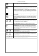
User Manual for SYSTEM 500M Key Functions The keys on the keyboard have the following functions: KEY DESCRIPTION 7 8 9 4 5 6 1 2 3 ESC 0 CLR The numeric keys are used to select the ID numbers of the monitors and cameras connected to the system, as well as video sequences, camera prepositions and remote sites. The CLR key resets all digits in the status display to 0 (zero).
User Manual for SYSTEM 500M The DISPLAY TEXT key is used to remove or insert text displayed by the selected Camera Station. Pressing the key ones removes text. Pressing the key again inserts the text. This function can only be used if BDR-55X Camera Stations are used. A The arrow keys are used for manual control of a pan and tilt unit. Only available for cameras controlled by Ernitec Camera Stations.
User Manual for SYSTEM 500M F1 F2 F3 The F1 and F2 keys can be used to control a relay or open collector output directly, if programmed to do so. F4 F5 F6 F7 F8 F9 F10 F11 AUX AUX VCR 1 VCR 2 The MENU key calls the main programming menu and can be used to exit the setup system while saving any programming changes made. If Adpro equipment currently is being controlled the MENU key will call the setup menu on the Adpro equipment being controlled.
User Manual for SYSTEM 500M The PHONE key is used in connexion with the VST 10CA Fast Scan to display the list of phone numbers, select a phone number and dial up. The AUDIO key is used in connexion with the VST 10CA Fast Scan to enable audio transmission from the transmitter site to the receiver site. Pressing the AUDIO key a second time will disable the audio transmission again. Pressing the ESC key immediately followed by the AUDIO key will enable audio transmission in the opposite direction, i.e.
User Manual for SYSTEM 500M Camera Select and PTZ-Camera Control The PTZ functions listed below are also available for PTZ cameras remotely connected to the VST 10CA Fast Scan transmitters; refer to the Operation section in the VST 10CA Manual Select Camera If Camera 3 is to be displayed on Monitor number 1 (SYSTEM 500M only): 1 ð ð 3 ð 3 ð SYSTEM 500M Select monitor number 1 VST 10CA Select camera number 3 Select channel number 3 Select Camera for PTZ-Control If Camera 4 is to be displayed and con
User Manual for SYSTEM 500M Take PTZ-Control* To control the PTZ functions on a camera present on the monitor selected by this keyboard: Take control* Warning*: The MON key should not be used in connection with cameras connected to the VST 10CA, since monitor operation is disabled while controlling Adpro equipment. Cameras connected to the VST 10CA can be PTZ-operated when displayed without further key strokes.
User Manual for SYSTEM 500M Pan Camera If the camera should be panned left or right, press: 1500M/1502M 1501M/1503M 1500M/1502M Pan left 1501M/1503M Pan right JOYSTICK NOTE: When controlling a variable speed Pan/tilt, BDR-575 or ICU, pushing the joystick towards its extremes will increase speed.
User Manual for SYSTEM 500M Call Preposition To call preposition number 3, press: 3 ð Call preposition number 3 Sequence prepositions To start sequence prepositions on the currently controlled camera, press: Sequence prepositions Remove text Remove the text generated by the currently controlled Camera Station: A ? Front panel 150XM Remove or Insert text from camera station Activate auxiliary function Activate an auxiliary relay in the currently controlled Camera Station: 2 Front panel 2 ð AUX
User Manual for SYSTEM 500M Monitor Operation and Time and Date Note: If one of the following messages is shown on the keyboard display: VMD control mode, VMF control mode or VST control mode the ADPRO key must be pressed in order to leave this mode before monitor operation is possible.
User Manual for SYSTEM 500M Set Time and Date To set the Time and Date, use the keys as shown: ESC ð = SET TIME/DATE Call Time and Date set-up DAY : 00 MONTH : 00 Use the TILT UP or TILT DOWN keys to find the item to set. Press the MONITOR key, enter the new data and press the MONITOR key once more. Continue with the next item. Press the T/D key to exit the Time and Date set-up.
User Manual for SYSTEM 500M Change Dwell Time To change the Dwell Time for sequence number 8: ESC ð = START SEQUENCE Call Dwell Time set-up SEQ ID: 000 DWELL TIME The default factor is 10, meaning that the sequences will be running with the specified dwell times; with the dwell time factor set to 5 the dwell times will be halved or, in other words, the sequence will be executed at double speed. Minimum factor is 3.
User Manual for SYSTEM 500M Alarm Operation Clear Alarm To clear a local alarm, press: Removes the alarm present on the local alarm group monitor(s) Clear Alarm in another group To clear an alarm belonging to another alarm group.
User Manual for SYSTEM 500M Alarm Status Alarm Status Get access to alarm status: ESC ð = ALARM STATUS Call Alarm Status menu PASSWORD ( 4 DIGIT ) * KEY IN YOUR 4 DIGIT PASSWORD (Level 1 Password) PRESS (ESC) TO QUIT Password Key in a 4 digit Password: ð 0 Open Field 0 0 0 ð Enter Password (Level 1 Password) = Close Field ALARM STATUS *ACTIVE ALARMS ALARM ZONES ALARM INPUT REMOTE ALARMS PRESS (ESC) TO QUIT The Alarm Status menu gives access to the following options: Active Alarms This sub
User Manual for SYSTEM 500M Alarm Zones From this sub-menu it is possible to enable/disable Alarm Zones: ð Move Cursor to ALARM ZONES, using arrow keys, or joystick. = ALARM ZONE STATUS 1: *ENABLED 2: ENABLED 3: ENABLED 4: ENABLED 5: ENABLED 6: ENABLED 7: ENABLED 8: ENABLED Press MON to call ALARM ZONES menu Use the TILT UP or TILT DOWN keys, or JOYSTICK, to position the cursor on an Alarm Zone, and press the MON key to open the field.
User Manual for SYSTEM 500M Operation of Adpro equipment The Adpro operating functions can only be accessed when the LEVEL 1 password is known by the operator. In order to set-up the Adpro equipment the LEVEL 2 password is needed. Note: The Adpro equipment can only be operated using 1502M/1503M keyboards. Setting the Keyboard Access Level In order to enter the Keyboard Access Level menu, press: ESC ð ADPRO = KEYBOARD ACCESS LEVEL Set the keyboard Access level.
User Manual for SYSTEM 500M Operation of Integrated Camera Unit (ICU) Some of the keys on the 1501M/1503M keyboards are reserved for special ICU functions.
User Manual for SYSTEM 500M Macro playback Macros can be recorded, and played back on the 1502M/1503M keyboards In order to playback a macro: 8 ð Playback macro number 8 If no macro has been assigned to the selected number, the following message is shown in the keyboard display: Macro empty. For information on how to record macros, please refer to the Keyboard manual.
User Manual for SYSTEM 500M Error Messages The SYSTEM 500M and/or the keyboards are able to display text messages for user guidance only and as error messages. Note: Certain error messages are displayed on monitor 1 only e.g. when downloading new settings from the SYSTEM 500M Set-up program. It is therefore recommended to have a camera displayed on the monitor 1 constantly. ALARM OUT OF RANGE The alarms are received on a serial RS-232 port from an external source according to the Ernitec alarm protocol.
User Manual for SYSTEM 500M KBD ## IN CONTROL An operator has tried to PTZ- or Adpro-operate a camera which currently is operated from another keyboard - keyboard number ##. Try to override the other keyboard by pressing the MON-button again. KBD ## USES MONITOR An operator has tried to select a monitor which currently is selected by a keyboard with a higher priority - the monitor is therefore not accessible.
User Manual for SYSTEM 500M VMD CONTROL MODE The keyboard is currently controlling a VM12 Video Motion Detection module. In order to operate the SYSTEM 500M; e.g. selecting a new monitor, the ADPRO key must be pressed in order to leave the VMD control mode. VMD MASTER NOT SET SYSTEM 500M can not find any VMD Master (Chassis 0, Slot 1). VMF CONTROL MODE The keyboard is currently controlling a VM30 Frame Store module. In order to operate the SYSTEM 500M; e.g.
User Manual for SYSTEM 500M GB - Page 24 Number 2822-00025
User Manual for SYSTEM 500M 7 8 9 4 5 6 1 2 3 ESC 0 CLR ADPRO DET ON DET OFF MODE 1/2 F1 F2 F3 F4 7 8 9 4 5 6 1 2 3 ESC 0 CLR INS MENU AUTO DEL SHIFT AUX VCR 1 AUX VCR 2 ? 1501M F5 MENU F6 F7 INS AUTO F8 F9 ON OFF F10 F11 F12 DEL SHIFT AUX VCR 1 AUX VCR 2 ? 1503M Number 2822-00025 GB - Page 25
User Manual for SYSTEM 500M GB - Page 26 Number 2822-00025
User Manual for SYSTEM 500M 7 8 9 4 5 6 1 2 3 ESC 0 CLR ADPRO DET ON DET OFF MODE 1/2 F1 F2 F3 F4 7 8 9 4 5 6 1 2 3 ESC 0 CLR MENU AUX VCR 1 AUX VCR 2 ? 1500M F5 F6 F7 F8 AUX VCR 1 AUX VCR 2 F9 ON OFF F10 F11 F12 MENU ? 1502M Number 2822-00025 GB - Page 27