MEK 2 Service manual 0740 800 094 020531
LIST OF CONTENTS Page READ THIS FIRST . . . . . . . . . . . . . . . . . . . . . . . . . . . . . . . . . . COMPONENT DESCRIPTION . . . . . . . . . . . . . . . . . . . . . . . . CONNECTION DIAGRAM . . . . . . . . . . . . . . . . . . . . . . . . . . . . DESCRIPTION OF OPERATION . . . . . . . . . . . . . . . . . . . . . . 1 2 3 4 5 6 7 8 9 10 11 Power supply . . . . . . . . . . . . . . . . . . . . . . . . . . . . . . . . . . . . . . . . . 2--stroke / 4--stroke . . . . . . . . . . . . . . . . . . . . . . . .
WARNING ! STATIC ELECTRICITY can damage circuit boards and electronic components. ESD S Observe precautions for handling electrostatic sensitive devices. S Use proper static--proof bags and boxes. WARNING ARC WELDING AND CUTTING CAN BE INJURIOUS TO YOURSELF AND OTHERS. TAKE PRECAUTIONS WHEN WELDING. ASK FOR YOUR EMPLOYER’S SAFETY PRACTICES WHICH SHOULD BE BASED ON MANUFACTURERS’ HAZARD DATA. ELECTRIC SHOCK -- Can kill S Install and earth the welding unit in accordance with applicable standards.
COMPONENT DESCRIPTION This component description refers to the connection diagram. In the description of operation on page 7 there is a more detailed description of the components and their function. AP01 Main circuit board with control electronics. C01 Capacitor 0.1 ←F 125 VAC, decoupling. G01 Tachogenerator, incorporated in motor M01. M01 Motor, rated voltage 24 V. R3 Potentiometer, for setting the burn--back time. RP01 Potentiometer, 10 kτ, for setting the wire feed speed.
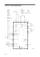
CONNECTION DIAGRAM MEK 2 The numerals 1 -- 11 refer to the description of operation.
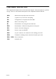
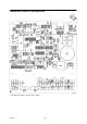
DESCRIPTION OF OPERATION cmek2e02 Component positions, circuit board AP01 cmek2de1 -- 6 --
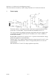
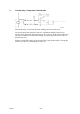
Sections 1 to 11 below refer to the diagram on page 5. The circuit board is screened by a metal casing, connected to 0 V in the wire feed unit. 1 Power supply cmek2e09 The feeder obtains a 42 V supply from the control power supply transformer in the power unit via contact XP01. Its power demand at maximum load is 3.5 A. 42 V AC is used for the welding torch trigger switch and as the power supply to the gas solenoid valve and the main contactor. In addition, 42 V is also available on contacts H01 and H02.
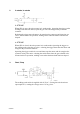
2 2-- stroke / 4-- stroke cmek2e08 2--STROKE When SW1 is open, the unit operates in 2--stroke mode. Operating the trigger on the welding torch starts the motor, opens the gas valve and energises the power unit contactor. Releasing the trigger stops the motor, de--energises the contactor and closes the gas valve. If burn--back is in operation, welding ceases when the burn--back time has elapsed. 4--STROKE When SW1 is closed, the unit operates in 4--stroke mode.
4 Current relay, Creep start / Normal start cmek2e03 The current relay is activated when the welding current exceeds 20 A. Creep start means that the motor runs at 1.9 m/minute until the current relay operates, after which the speed increases to the set speed. If the current relay does not operate within one second after starting, the motor speed increases to the set speed in any case. Selector switch SW2 on the circuit board selects Creep Start On/Off.
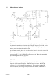
5 Motor driving / braking cmek2e12 DRIVING The motor is powered from the smoothed +60 V supply. Motor speed is controlled by pulse width modulation of transistor Q1. The pulse frequency is 12 kHz, and the maximum on--time is 97% of the pulse cycle time. During the pulse spaces, the motor current freewheels through diode D8. At 24 V motor supply voltage, the wire feed rollers’ speed is 160 r/min. A wire feed speed of 20 m/min. requires a roller speed of 212 r/min.
6 Tachometer input cmek2e06 Tachometer G01 is fitted in the motor casing. Tachometer output frequency is 796 Hz for a wire feed speed of 20 meters per minute. Comparator IC4:2 converts the sine wave signal from the tachometer to a square wave at the same frequency. 7 Burn-- back time cmek2e05 The burn--back time is the time from when motor braking starts until the main contactor in the power unit opens. It can be adjusted between 0 and 0.
9 Gas valve cmek2e11 The gas valve is connected to board contacts G04 and G05. The valve is energised via triac TC1. 10 Activation, contactor cmek2e10 The start signal to the power unit is connected to board contact G03. The contactor is energised via triac TC2. 11 Processor The processor incorporates EPROM memory in which the machine’s program is stored. The processor monitors the wire feed speed. If the speed deviates from the set speed by more than 1.
TECHNICAL DATA Power supply 42 V 50 -- 60 Hz Power requirement 150 VA Feed speed 1.9 -- 20 m/min Pistol connection EURO Max. diameter of wire bobbin 300 mm Weight 15 kg Dimensions (l x w x h) 645 x 240 x 480 mm WARNING There is a risk of tipping if the MEK 4 is fitted with a counterbalance arm. Secure the equipment, especially if used on an uneven or sloping surface. Limit the angle of rotation of the wire feed cabinet using the straps supplied.
SETTING THE WIRE FEED PRESSURE Start by checking that the wire can run freely through the wire liner, and then adjust the pressure of the wire feed rollers. It is important that the pressure is not too high. Figure 1 Figure 2 To check for correct feed pressure, feed the wire out against a piece of insulating material, such as a piece of wood. With the pistol held about 5 mm from the wood (Figure 1), the drive rollers should slip.
CONTROL PANEL AND CONNECTIONS 1. Cooling water connections (only --883 model). 2. 3. Gas connection. Connector for control cable from the power unit. Connector for welding current cable from the power unit. Potentiometer, wire feed speed 1.9 - 20 meter per minute. Cooling water connections to/from the welding gun (only --883 model). Strap securing points. The strap must be used to secure the wire feed unit to the power unit during transport. Hole for fitting wire liner from the ESAB Marathon Pac.
ACCESSORIES Item no. Ordering no. 1 469 789--880 2 469 836--880 2 469 836--885 469 836--881 469 836--886 Connection set, 1.7 meter. When connected to LAX 320/380 Connection set, 1.7 meter. When connected to LAX 380W Connection set, 8 meter. When connected to LAX 320/380 Connection set, 8 meter.
MEK 2 Edition 020531 Spare parts list Valid for serial no. 510 --xxx--xxxx to serial no. 826--xxx--xxxx Ordering numbers for MEK 2 0455 590 881 0455 590 883 MEK 2 MEK 2 Without water connection With water connection Spare parts are to be ordered through the nearest ESAB agency as per the list on the back of the cover. Kindly indicate type of unit, serial number, denominations and ordering numbers according to the spare parts list.
MEK 2 Edition 020531 Item Qty Ordering no.
MEK 2 bm17s11a Edition 020531 -- 19 --
MEK 2 Edition 020531 C = component designation in the circuit diagram Item Qty Ordering no.
MEK 2 bm17s11a Edition 020531 -- 21 --
MEK 2 Edition 020531 C = component designation in the circuit diagram Item Qty Ordering no.
MEK 2 bm17s11a Edition 020531 -- 23 --
NOTES notes -- 24 --
notes -- 25 --
ESAB subsidiaries and representative offices Europe AUSTRIA ESAB Ges.m.b.H Vienna--Liesing Tel: +43 1 888 25 11 Fax: +43 1 888 25 11 85 BELGIUM S.A. ESAB N.V. Brussels Tel: +32 2 745 11 00 Fax: +32 2 726 80 05 THE CZECH REPUBLIC ESAB VAMBERK s.r.o. Prague Tel: +420 2 819 40 885 Fax: +420 2 819 40 120 DENMARK Aktieselskabet ESAB Copenhagen--Valby Tel: +45 36 30 01 11 Fax: +45 36 30 40 03 FINLAND ESAB Oy Helsinki Tel: +358 9 547 761 Fax: +358 9 547 77 71 FRANCE ESAB France S.A.